diy solar

diy solar

Solar pergola -advice needed

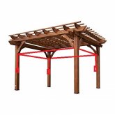
Here's what I would do from a design standpoint. Build it on 18 inch taller posts. Where you see the red lines on the photo imagine 2x4s. And the space above them wood to box it all in. That gives you a cavity where the charge controller, batteries, DC fuse block and inverter (if you use one to offer AC) can be stored. Away from vandals who might steal the stuff. (Remember, if they want it bad enough, they will get it. You can only deter. ) Then just run conduit down all 4 of those posts and put in an outlet box. Something like this. Put the panel(s) on top, voila. Thieves would need a ladder, tools, etc..... Not a grab and dash situation.

pergola.jpg
 
Here's what I would do from a design standpoint. Build it on 18 inch taller posts. Where you see the red lines on the photo imagine 2x4s. And the space above them wood to box it all in. That gives you a cavity where the charge controller, batteries, DC fuse block and inverter (if you use one to offer AC) can be stored. Away from vandals who might steal the stuff. (Remember, if they want it bad enough, they will get it. You can only deter. ) Then just run conduit down all 4 of those posts and put in an outlet box. Something like this. Put the panel(s) on top, voila. Thieves would need a ladder, tools, etc..... Not a grab and dash situation.

View attachment 1026
Wow! thank you so much @eddie1261 for your effort(drawing and etc.) it is a good idea to use that space as you said.
 
Hi all,
So some update regarding the project.

i will get the following part(for free☺)
  1. Mounting system(2 PC): renusol.com/en/pv-mounting-systems/trisole-triangular-mounting-and-racking-system-for-pv.html
As you can see it's pretty close to my system requirement.
i would like to put all the components in a IP protected box under the table pergola (and make all the sockets and USB port from that box)
So what is missing now:
1.Find the right IP protected box(from metal)
2.IP protected USB and AC sockets
3.MC4 connectors and cables(4 mm^2 or 6 mm^2)
4. Circuit beaker 50A
5.Fuses/Fuse box?

If you have any suggestion/recommendation from the list above what should i buy(amazon links will be the best) i would very appreciate
or if i missed some component i will also appreciate any help ! ???


Thanks !
 
I was just looking at the A & B photos ...
A)
index.php
B)
index.php


People won't steal something if they don't know it's there, and aren't to likely to vandalize what should be the only visible elements, electrical receptacles, because of shock danger (BTW, Since it's outside and wet, be sure to use GFCIs).

What struck me was that B was far friendlier in that it offered students a place to meet and work together. It has the attraction of a more social setting as multiple stations look good together and each can accommodate multiple groups of students. Any gear can be hidden inside the table's pedestal. But the heavy solar panel balanced at a single point/axis seems to be an engineering challenge you might want to avoid, those panels can grab a lot of wind and the Canadian Solar you selected only have their strength rating when attached at 4 specific points.

In the original A photo the pergola has a deck, that adds tremendously to it's beauty; it's also a great place to hide stuff beneath such as batteries (that is you can either dig out under the pergola or raise it up a foot or so).

The pergola is also a solid foundation for a number of solar panels and can be very firmly anchored. The pergola, although pretty, feels like an "empty" space. The empty feeling could be altered by putting a table and benches under it; or perhaps benches along the long run with some interesting center feature? To keep the ascetics, you can hide the solar panel's wiring inside a hollow down-post (and all the gear safely hidden underneath the pergola).

In terms of space utilization, you probably couldn't have more than one pergola, but you could have multiple "B" stations. I believe your idea is to combine the two, that is have a central pergola (A) that is surrounded by little work-islands (B). In that case, I'd get rid of the panels on the B stations (with their engineering problems) and just run power to them underground from the pergola. That would also reduce costs as each table wouldn't need it's own inverter, batteries, etc. The pergola would be the centralized power generation, storage, and distribution center, the "B" workstations just outlets.
 
Last edited:
Hi all,
So some update regarding the project.

i will get the following part(for free☺)
  1. Mounting system(2 PC): renusol.com/en/pv-mounting-systems/trisole-triangular-mounting-and-racking-system-for-pv.html
As you can see it's pretty close to my system requirement.
i would like to put all the components in a IP protected box under the table pergola (and make all the sockets and USB port from that box)
So what is missing now:
1.Find the right IP protected box(from metal)
2.IP protected USB and AC sockets
3.MC4 connectors and cables(4 mm^2 or 6 mm^2)
4. Circuit beaker 50A
5.Fuses/Fuse box?

If you have any suggestion/recommendation from the list above what should i buy(amazon links will be the best) i would very appreciate
or if i missed some component i will also appreciate any help ! ???


Thanks !


Looks great except the battery is way too small, and I wouldn't recommend a gel cell. Your panels and controller will be charging at near/over 40 amps, and that battery can't handle more than a 10amp charge (preferably lower)....you'll smoke that battery. Plus it probably won't have much run time with the inverter. Any way you can find two 6v 225ah golf cart batteries? Or preferably a 100ah+ lithium?
 
Dear @svetz and @SolarRat
first thank for taking you time and answer my post:).
So regarding what you wrote, just 2 important things about the project
1.we have a very tiny budget from the university so every help that has been given to us is wellcome , as i said they give us the all components for free.
2.the design is already done and it will be the A picture -we don't have any other option.

Some comments about what you wrote:

1.Thank you or the advice to use GFCI-this is the first time i hear about that.

2....In the original A photo the pergola has a deck, that adds tremendously to it's beauty; it's also a great place to hide stuff beneath such as batteries (that is you can either dig out under the pergola or raise it up a foot or so). ... i don't think it's a good idea because there will be rain and etc.
my idea is to buy some box(metal) and put all the components inside and place it below the table(extra protection from water)

3.....battery is way too small, and I wouldn't recommend a gel cell. Your panels and controller will be charging at near/over 40 amps, and that battery can't handle more than a 10amp charge (preferably lower)....you'll smoke that battery. Plus it probably won't have much run time with the inverter. Any way you can find two 6v 225ah golf cart batteries? Or preferably a 100ah+ lithium? as i said ...low budget
Can you please explain why the battery can't hold more than 10 amps ?
and
why "probably won't have much run time with the inverter"?

Please give me some more recommended components that you would use in this project (except the big 4-panels,CC,inverter,battery)

Thanks .
 
my idea is to buy some box(metal) and put all the components inside and place it below the table(extra protection from water)
The A photo doesn't have a table, but that would certainly fill in the "empty" space. Do you have any images representing the final idea?

I'm thinking the table top could be on a pedestal, and all the gear hidden inside. The wire from the panels hidden in a "hollow" support post (e.g., four 2x4's rather than a single 4x4's so there's a hidden hole in the center) then run underneath to the pedestal. This way you don't have to worry about squirrels or students picking at the wire's insulation. I'd also use a sealed inverter so you don't have to worry about ventilation/weather.

As to the battery size, it really depends on how much power you expect to be drawn during non-sun hours. For example, let's say you want six students with 6 laptops, each drawing 50 watts of power and you expect it to be used on average of 10 hours a day. Let's also say you want a string of led christmas type lights to run 24x7 to jazz it up and they use 10 watts. So you need:

6 laptops x 50 watts x 10 hours = 3000 watt hours
24 hrs x 10 watts = 240 watt hours.

Let's assume an 80% efficiency for the battery, inverters, and wiring; so total battery power is 3240 / .8 = 4000 watt hours.

Let's assume from the insolation map you get 5 for the equivalent "full" sun hours, so you'd need 3240 / 5 / .8 = 810 watts of panels. Or 3 of the 325 watt Canadian Solar panels.

For the battery, let's assume 12V, so 4000 / 12 ~= 350 Ah. Or if you want an extra day to insure it works through a gloomy day that's 700 Ah @ 12V.

If you want to stick with those 60 Ah Victron Gel lead acid batteries you'd want to limit the depth of discharge to 50%, so that bumps it up to 700 or 1400 Ah. At 60 Ah per battery, you'd need 12 to 24 and that's a lot to put in parallel. Even then you'll probably only get 5 years out of them. This is where lithium shines, longer cycles and greater depth of discharge.

If you want it to work in cold weather, you'll need to look at the data sheet to see how much it'll lose with temperature. You should probably also check the draw rate; a 60 Ah lead acid battery is only 60 Ah if you're pulling less than 3 amps from each battery. See the Battery FAQ for all the fun details.
 
Last edited:
Might be cheaper to use a GFCI breaker rather than GFCI outlets...although when they trip it'll take someone who knows what they're doing to reset them as the breaker wouldn't commonly be exposed to students. Might be just as well, those GFCIs can be tough to reset when left out to weather.

The nice thing about that is you could use tamper resistant plug/USB outlets.

Note the lack of screws and USB ports of this model. IPads tend to use a lot of amps, so if they're popular on campus make sure the USB ports can supply enough juice to them.

61aVcvZXgsL._AC_SL1500_.jpg

I don't know if anyone makes a usb/ GFCI version. Of course, you'd be more efficient if the USB was off the battery rather than the inverter; so two sets of plugs might make sense.
 
Last edited:
You'll also want some sort of tamper resistant weatherproof cover for the outlets:

41BDTNC1iTL._AC_.jpg
I'd stay away from anything to gimmicky/expensive...these are going to break over time.
 
Can you please explain why the battery can't... [be charged faster] ...than 10 amps?
From the Battery FAQ, batteries have a C-Rate for charging and discharging. The Battery's datasheet can tell you what it is; exceeding it will damage the battery (true for lead or lithium).
 
Make sure whoever is wiring it up knows what a "drip loop" is. ;)
 
...Find the right ... box(from metal)...
Normally, I like metal for electrical as when properly grounded it's far likelier to trip the breaker if there's a short. But, being outside in the wet/damp and around students I'd go with non-conductive wood; there can be low amp shorts that won't trip the breaker but can still shock you. You still want to bond the grounds of all the devices of course.

Speaking of wood outside, you'll probably be using some sort of pressure treated wood. Be sure to check the chemistry against any metals being used as some are susceptible to chemical attack from the wood's preservatives. This applies to fasteners like screws, but also to things like the rack that will be mounted to the top of the pergola.

... i don't think [a hole is]... a good idea because there will be rain and etc.
A hole in the ground that's above the water table, covered so rain doesn't go in, and is properly setup (a brim so flowing ground water is diverted around it) should stay dry. You can also raise the pergola floor rather than dig a hole. If the batteries are the only thing under the floor and the bottom area gets wet occasionally it won't hurt anything if the foundation is solid. Just thought I'd mention it as the physical space of the batteries for the watts in the above post will take up quite a bit of room (they could also sit under benches in the pergola).
 
In sequence, starting from the panels, here's the electrical items (Please double check me guys/gals):
  1. Panels
  2. Earthing Rod (2 bonds: one from the Panels, one from the Inverter)
  3. Optional: DC disconnect (convenient to de-energize/isolate the SCC)
  4. Solar Charge Controller (grounded to inverter)
  5. DC disconnect
  6. Battery bank (negative ground to inverter)
  7. Optional: Low Amp energizer (this is a small fused wire with a doorbell pushbutton/light - it's to let power flow slowly into the inverter rather than all at once to charge the big caps before throwing the DC breaker)
  8. DC Breaker
  9. Low Voltage Cutoff
  10. Inverter (neutral bonded to ground, ground to earthing rod)
  11. GFCI Breaker
  12. Outlets
Hmmm... I know I'm missing something. Will did something with the low-voltage relay cut off on the Victron... anyone remember what that was about?
 
Last edited:
Hello,

I won in sustainability contest in my university, my idea is to build a solar pergola(student can sit there and combination of A+B pictures)
i know for sure that this pergola will have USB sockets(for charging) but i also wanted to add AC sockets for charging computers but if you take in to account the human responsibility(some one can harm it) and the environmental condition(rain..snow) it't really become dangers
of course i can plan all the IP67/8 enclosures and fusses and etc. , but is it really good idea ? from a safety point of view
what do you think ?
New laptops are often charged via USB C. They are not the standard 2.1 amps. You'll have to research their charge profiles. But this is a much safer option.
 
Hi Guys! Sorry for the delay in response(busy weeko_O)

So Thank you @svetz @SolarRat @erik.calco for the last comments.

From what i read and checked the Battery is totally not suitable for this sizing of my system?
I made some calculation based on the Datasheet:
As you already know i supposed to get the following battery:
1573484881080.png

1573484741193.png

1573484770946.png

The maximum charging current for my battery(based on the paragraph above and the chart % vs Temp):
the calculation is for 25 degrees
A)C/5=0.2C
B)60ah(rated)*0.8(Capacity at 0.2C)=48ah(new rated with 0.2C)
C)C/5=5hr
D)Max charging rate 48/5=9.6 amp

And my panels will produce 2*280=560 W ->500W after losses
The current after CC =>500/12=40 amp

are my calculation ok? i was wandering if i need to take in to account that the usable capacity is actually 50% (for longer battery life)

So as you said ..my current charging will be 4 times more then the max !!!
Couple of question regarding my situation:
1.What will happened to the battery if i will proceed with this installation? i assume that the excess of energy will go as a heat right? so it will explode?
2.Is there a safety feature on the CC that (or i can buy) that will eliminate this high current?
3.What is my options?
from what i see is
A)to make my battery larger(or more of the same) ?
B)to take smaller wattage panels?

Thank you again for your support!
 
There's a discussion on current limiters in another thread.

Are my calculations okay?
Don't forget that the panels put out more power when it's cold. See Figuring out how many panels in series and parallel based on your MPPT to see temperature compensation calculations for voltage (current compensation uses the same technique). You should also make sure that the panels won't provide too much voltage and current for the MPPT.

If you were worried about a little overcharging due to low temperatures, then what would happen is the batteries would heat up. But as it heated up their capacity would be restored which would make it okay for the normal C-rate. But the normal C-Rate is 60 / 5 = 12 amps and your panels would be putting out a lot more than that; which is why @SolarRat pointed the issue out. There's probably a temperature sensor on the MPPT to monitor the batteries and keep them from exploding; but better to size things correctly in the first place due to Murphy's law (anything that can go wrong will go wrong).

The typical solution is to add more batteries in parallel to divide the current or upsize them. This is the best solution as it fully utilizes the panels and makes the most power available for the students.

But, if you're really stuck with what you have you can cheat. For example, using only 1 panel would halve the current; that's not really enough of a current limit for your situation though.

If you really want to freak all the faculty & students out, you can use both panels and defy convention by NOT having them optimally south facing. You can oddly angle them such that one panel is picking up the early morning sun and the other is picking up the setting sun. For example one panel might face east and one might face west. The panels might be mounted at 80° to reduce the power from the noon time sun to acceptable levels. That gives you a greater power output throughout the day and with a careful angle you should be able to ensure the current never exceeds the maximum. If you go this route I'd suggest downloading/using SAM to figure the angle/azimuth that maximizes your overall daylight power and yet never exceeds the maximum amps.
 
Last edited:
Like I said on the previous page, the battery is way to small, for both the load and charge rate. Your calculations are correct. That gel battery won't last a month, and an explosion is not out of the question at that charge rate. With kids sitting around it, do not even try it. Get a bigger battery. I'm not a fan of AGM or GEL batteries, especially for solar. I much prefer FLA's, but in your situation (daily cycles, sealed enclosure, no maintenance, no gassing off in tight space near other electronics etc), your best option by far is LFP. But you can certainly get away with using anything bigger that you can get your hands on (afford).
 
I know I'm missing something. Will did something with the low-voltage relay cut off on the Victron... anyone remember what that was about?
@gnubie posted it in another thread:
...controller should not have PV input without battery present...
He said a lot controllers should have the PV disconnected if the battery becomes disconnected (e.g., low-voltage cutoff or fuse).
 
Hi @svetz @SolarRat thanks again for helping me. i will reply to your messages this weekend.

i just want to share the message that i got from the company( that giving me the free parts) tech support plus some files that they share -What you think about what they wrote?

In order to use all full potential of the system, they should have a 24 V system and 2pc of 100Ah battery in series. But because of the unique situation when they have free PV modules and a limited budget I suggest as follows:

- Use smaller Charge Controller https://pvtrade.eu/en/charge-controllers/6500061-smartsolar-mppt-10020.html. This is a controller with Bluetooth integrated for commissioning. The output current is limited at 20A max so a lot of energy during summer is lost but under this project that shouldn't be a problem.
- Use bigger battery https://pvtrade.eu/en/batteries/6500210-12v110ah-gel-deep-cycle-batt.html with 110Ah so it could withstand all the 20A charging current.
- A notice during installation, all of this equipment is for indoor installation

I attached a document about lead-acid battery and excel tool to check the Charge controller


https://drive.google.com/file/d/1NyHcO8jhQsiyQ8zVyWabopZr0onepYIS/view?usp=sharing
 

Attachments

  • Maximising lead acid battery life - Lesson.pdf
    1.3 MB · Views: 5
Back
Top