This is a simple offgrid isolated fridge system (not really meant for driving other appliances).
It is also realized with very usual components, just added a custom control board (very simple though)
As it is just a proof of concept, this test build goes a bit extreme :
:
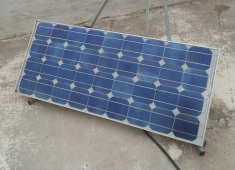
- 85W solar panel for 12V systems (used but still >90% output)
- old Solsum 8.8X charge controller (used, no mppt, but ok with this solar panel)
- 12V car battery (75Ah, not new but OK): as I never discharge more than 5%, this should last a while
- 600W modified sine inverter (a cheap one of those I repaired)
- tabletop fridge, compresor marked 50W , 2 bottles of 1.5l full of water in the freezer
- DIY control system: cost of components perhaps 10$: PCB, relay, 8pin microcontroller (attiny13), low power transistor, led, 4 resistors
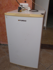
Here is the fridge:
Here is the power source:
And thess are the battery and controllers:
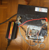
Some mods are needed:
- on this charge controller: take out the regulated 5V to supply the control board, take out charge (sun) led info, and battery status led info. With a more sofisticated controller, like my victon bluesolar you just want to read the serial port
- on the inverter: bring out the 2 on/off switch wires, this will go to the control board relay
- on the fridge: bring the thermostat wires out, they have to be separated from the motor wires as they will be read by the microprocesor.
Some comments about the fridge:
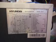
this is a very simple one: Hyundai MN11, 82l internal volume, 50W QD35Y compresor, thermostat is mecanical (no electronics).
- walls are only 4cm thick, and include condensers on the sides! (where the extracted heat is released). Compare this to the 9cm thick insulation of my DC chest fridge, with a separated and ventilated condenser.
- the internal lamp should be changed for leds able to work on battery voltage
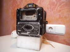
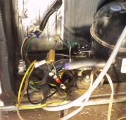
- At the beginning the fridge didn't always want to start from this inverter (just if still warm, but not too much!). I had no more powerful inverter, but managed to reduce the inrush current putting a resistor in serie with the starter PTR (equivalent would be to change the PTR from actual 15ohm value to 33ohm). Now starts fine in every condition
Starter (provisional !) mod:
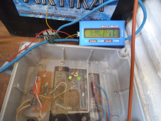
Control board (left), charge controller (right):
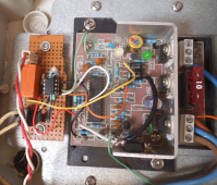
The logic implemented in the microcontroller is quite simple:
- always shutdown at night
- during daylight, start the inverter only when the battery reaches full load, and for a limited time
this is the most important feature to protect the battery: in this case you will always cycle from battery full to a limited discharge (no more than 5% in my case)
- of course, shutdown the inverter when the thermostat trips
- you can also extend the limited time if the battery stays at full load, shutdown immediately if the battery charge status drops too much, blink a led to show some info, enable a car socket if there is excess PV...
- as I did it with my DC fridge, the control board is fed from the charge controller, so its supply current has to be very low. Essentially driven by interrupts, this control board draws less than a milliamp.
Some measures, made with ac/dc current clamp:
inverter running with fridge attached draws 6.5Amps from battery @ 12.6V
AC current fridge running : 0.4A total, 0.01A goes to start winding
The solar panel has almost the best fixed orientation for actual season. Charge was measured at best 4.5A (but I'm not there all the day)
Yesterday (almost 12h daylight at this season), the fridge worked during 9x 35min cycles (weather sunny, but some haze) , and generated estimated 1.5l ice (room temperature 22ºC). That means ~= 430Wh energy used (supposing 6.5A @12.6V)
Today, very hazy,then cloudy, it worked no more than 5x 35min cycles (~=240Wh used). With 23ºC room temp, internal was still around 11ºC (good for beer!)
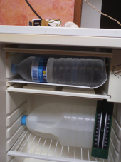
Time counter on top, min-max thermometer inside
Obviously, I would not put fish or meat in this fridge . Autonomy is too short, and cold is lost very quickly.
Repeating, this is more a test system to show how it is posible to run a fridge from PV with few resources.
With a better insulated fridge and more PV power (but limited by the charge controller), I am almost sure you would have a usable system.
We can compare this data with what my chest fridge controller(freecold RSI 150, ~=125l internal volume) recorded from the victron 75/15 attached to 340W panels:
yesterday 280Wh were harvested , today 270Wh, to run nothing more than the chest fridge (I blowed my inverter in a failed security test connecting it to mains )
)
The bigger chest fridge could almost have been run from the 85W panel with the old SolSum non mppt charge controller!
We can make some math to find out where the difference in efficiency comes from (next post)
It is also realized with very usual components, just added a custom control board (very simple though)
As it is just a proof of concept, this test build goes a bit extreme
- 85W solar panel for 12V systems (used but still >90% output)
- old Solsum 8.8X charge controller (used, no mppt, but ok with this solar panel)
- 12V car battery (75Ah, not new but OK): as I never discharge more than 5%, this should last a while
- 600W modified sine inverter (a cheap one of those I repaired)
- tabletop fridge, compresor marked 50W , 2 bottles of 1.5l full of water in the freezer
- DIY control system: cost of components perhaps 10$: PCB, relay, 8pin microcontroller (attiny13), low power transistor, led, 4 resistors
Here is the fridge:

Here is the power source:

And thess are the battery and controllers:

Some mods are needed:
- on this charge controller: take out the regulated 5V to supply the control board, take out charge (sun) led info, and battery status led info. With a more sofisticated controller, like my victon bluesolar you just want to read the serial port
- on the inverter: bring out the 2 on/off switch wires, this will go to the control board relay
- on the fridge: bring the thermostat wires out, they have to be separated from the motor wires as they will be read by the microprocesor.
Some comments about the fridge:
this is a very simple one: Hyundai MN11, 82l internal volume, 50W QD35Y compresor, thermostat is mecanical (no electronics).
- walls are only 4cm thick, and include condensers on the sides! (where the extracted heat is released). Compare this to the 9cm thick insulation of my DC chest fridge, with a separated and ventilated condenser.
- the internal lamp should be changed for leds able to work on battery voltage
- At the beginning the fridge didn't always want to start from this inverter (just if still warm, but not too much!). I had no more powerful inverter, but managed to reduce the inrush current putting a resistor in serie with the starter PTR (equivalent would be to change the PTR from actual 15ohm value to 33ohm). Now starts fine in every condition
Starter (provisional !) mod:

Control board (left), charge controller (right):

The logic implemented in the microcontroller is quite simple:
- always shutdown at night
- during daylight, start the inverter only when the battery reaches full load, and for a limited time
this is the most important feature to protect the battery: in this case you will always cycle from battery full to a limited discharge (no more than 5% in my case)
- of course, shutdown the inverter when the thermostat trips
- you can also extend the limited time if the battery stays at full load, shutdown immediately if the battery charge status drops too much, blink a led to show some info, enable a car socket if there is excess PV...
- as I did it with my DC fridge, the control board is fed from the charge controller, so its supply current has to be very low. Essentially driven by interrupts, this control board draws less than a milliamp.
Some measures, made with ac/dc current clamp:
inverter running with fridge attached draws 6.5Amps from battery @ 12.6V
AC current fridge running : 0.4A total, 0.01A goes to start winding
The solar panel has almost the best fixed orientation for actual season. Charge was measured at best 4.5A (but I'm not there all the day)
Yesterday (almost 12h daylight at this season), the fridge worked during 9x 35min cycles (weather sunny, but some haze) , and generated estimated 1.5l ice (room temperature 22ºC). That means ~= 430Wh energy used (supposing 6.5A @12.6V)
Today, very hazy,then cloudy, it worked no more than 5x 35min cycles (~=240Wh used). With 23ºC room temp, internal was still around 11ºC (good for beer!)
Time counter on top, min-max thermometer inside

Obviously, I would not put fish or meat in this fridge
Repeating, this is more a test system to show how it is posible to run a fridge from PV with few resources.
With a better insulated fridge and more PV power (but limited by the charge controller), I am almost sure you would have a usable system.
We can compare this data with what my chest fridge controller(freecold RSI 150, ~=125l internal volume) recorded from the victron 75/15 attached to 340W panels:
yesterday 280Wh were harvested , today 270Wh, to run nothing more than the chest fridge (I blowed my inverter in a failed security test connecting it to mains
The bigger chest fridge could almost have been run from the 85W panel with the old SolSum non mppt charge controller!
We can make some math to find out where the difference in efficiency comes from (next post)


