diy solar

diy solar

Time for a new weather station?

Found 4 of them, 400EP18A and they are 40 kHz... but are they usable?
This will be fun, no clue what I'm doing.... ;-)

They have a max of 20Vrms and in the datasheet they show 110 dB at 10V.
1595077103720.png
10 Vrms means an irregular square wave (pwm with duty) over 10V if converting into more a sine wave. That could be a problems as the circuit probably won't be over 5V.

Need to study up on these.
 
Last edited:
So, what sort of dB would be generated at 3.3V and how many volts should the receiver see? Assuming I’m interpreting this correctly…

Datasheet Facts
Transmitting Sound Pressure Level
at 40.0Khz; 108 dB min, 0dB re 0.0002Pbar per 10Vrms at 30cm
Receiving Sensitivity at 40.0Khz 0dB = 1 volt/μbar -75dB min.

From the ref:
Determining SPL at the front end of Receiver​
SPL loss for 3 Vrms driving voltage = 20 * log (3V / 10V) = -10.46 dB​
SPL Gain at 10 cm = 20 * log (30 cm / 10 cm) = 9.54 dB​
Wave absorption = ~ .1886 dB/m * .1 = .02 dB (page 4)​
The SPL at 10 centimeters becomes = 108 – 10.46 + 9.54 - .02 = 107 dB​
Converting SPL to μbar: 107 dB = 20 * log ( X / 0.0002 μbar)​
X = 45 μbar​
Determining Receiver Sensitivity in Volts/μbar​
Converting Sensitivity to Volt/μbar: -75 dB = 20 * log ( X / 1 Volt/μbar)​
X = 0.178 mV/μbar​
Voltage generated under 0.178 mV/μbar = 0.178 mV/μbar * 45 = 8 mV​
At 5V it the receiver would be:
Determining SPL at the front end of Receiver​
SPL loss for 3 Vrms driving voltage = 20 * log (5V / 10V) = -6.02 dB​
The SPL at 10 centimeters becomes = 108 – 6.02 + 9.54 - .02 = 111.5 dB​
Converting SPL to μbar: 107 dB = 20 * log ( X / 0.0002 μbar)​
X = 75.16 μbar​
Determining Receiver Sensitivity in Volts/μbar​
Voltage generated under 0.178 mV/μbar = 0.178 mV/μbar * 75.16 = 13 mV​
Update: The Cortex M7 ADC has 12 bits and covers -3.3 to 3.3, so steps of 1.6 mV? If so, wouldn't need a transistor to boost the receiver signal for a chirp, but to curve match we'd get a better fit with a transistor.
 
Last edited:
You can send square wave into US transducers without a filter ;) If you want a bit more efficency you can add an inductor which should be calculated to have the resonant frequency of the resulting LC network (a piezo transducer is basically a capacitor) equal to the tuned frequency of the transducer (usually 40 kHz).

The transducers usually need a lot more voltage than 3.3 V to do something useful, something like 12 or 15 V is generally a minimum. But in your application the receiver is close to the the emitter so 3.3 V may be do-able. The simplest is to try it as maths for that are a PITA and there's a lot of variables to ruin your accuracy anyway. Just feed one 40 kHz and experiment with directivity, distance, etc... looking at the output of the other one.

IBut 'd recommend you to use a ready made time of flight telemeter who already does all the work and outputs a 0-5 V voltage proportional to the distance (wind speed in your case) or even talks directly via serial, I2C, SPI, ... the only modification would be to unsolder one of the transducer to put it in front of the other some distance appart. Just be careful of the minimal distance measurable, usually something like 10-20 cm, they need to be farther appart than that obviously.
 
Thanks BiduleOhm!

...You can send square wave into US transducers without a filter...
Really! Cool!
What would the wave form look like on the receiving side? The way I was planning to get the delta time was to grab a few receiver voltages, then solve for wave offset (see post #16). But I was assuming both waves would be pretty close to a sine wave.

...transducers usually need a lot more voltage than 3.3 V to do something useful, something like 12 or 15 V is generally a minimum. B... simplest is to try it as math...
Did that in the post #22. Came up as 8 mV at the reciever for 3V at the transmitter and 13 mV for 5V.... assuming I did it right... and there's no minimum voltage to fire the p-crystal.

...I'd recommend you to use a ready made time of flight telemeter ...
More stuff to research! ;-)
 
Last edited:
Found a couple of ToF chips: The $6 TDC7201 and the $10 ISL29501IRZ-T7A (although that looks like it's for optical circuits).

The cheaper one has two channels, looks like they operate as stop watches, start/stop pins, 3.9V max, then an SPI interface to get the time (accurate to picoseconds).

Seems like it would be a crime not to use it... except... all the pins are on the bottom? How are you supposed to solder that?? Socket for it or am I going to have to get an easy bake oven? It's a 5x5 (25 pin) FBGA (fine ball grid array).

The $3 TDC7200 has a single channel and a TSSOP(14) package, so probably easier to work with. 55 ps resolution. 2 to 3.6V.

Similarly the $6 MAX35101 has an accuracy of 20 ps and a 32-TQFP Exposed Pad.
 
Last edited:
You'll get a sinus pretty much. Use the zero crossings (with some hysteresis to negate noise) as they are easy to detect and pretty much wave-form independent. But something better would be to have something like a Schmitt trigger after the receiver so you have a nice square wave to use (and then you can use a digital I/O, no need of ADCs who are slow and add inaccuracies).

Well, even with 1 V you'll get something on the other side... the question is what is the SNR? because noise will likely be an issue at one point or another. That's why I recommend a higher driver voltage (pro-tip: use a H bridge so you can have 10 Vpp from a single rail 5 V for example), you'll have a higher SNR and you'll be less likely to have noise problems.

Well, BGA are a PITA but FBGA is even worse... don't get those unless you have proper reflow equipment and you know what you're doing. TSSOP is somewhat a PITA as it's pretty fine pitch but is ok as you can use drag soldering anyway, ideally you want SOIC or bigger for hand soldering ;)

Accuracy of a few dozens of ps for a few $? I love today's world :D

But I meant more a ready made module, like this https://www.ebay.com/itm/RCW-0001-M...543160?hash=item52082de2b8:g:ICAAAOSw93ZayN1q they're cheap and already have everything, you just need to do the software part ;)
 
...Use the zero crossings (with some hysteresis to negate noise) as they are easy to detect and pretty much wave-form independent.
How do you detect zero crossings on the receiver?
The earlier solution (post #17) uses sampling to get enough data points to calculate the equation of the second waveform with confidence (there's only 2 important factors: frequency and offset; where frequency is known), but I like the idea of using the crossings as the transmit signal could be a square wave (the received signal still couldn't be though).

... the question is what is the SNR? because noise will likely be an issue at one point or another. That's why I recommend a higher driver voltage (pro-tip: use a H bridge so you can have 10 Vpp from a single rail 5 V for example), you'll have a higher SNR and you'll be less likely to have noise problems.
I was thinking a DC/DC Converter could be added if needed to increase that; wasn't sure as the max voltage (20V) was only 4x the 5V, probably because they're so close together:

Determining SPL at the front end of Receiver​
SPL loss for 20 Vrms driving voltage = 20 * log (20V / 10V) = 6 dB​
The SPL at 10 centimeters becomes = 108 + 6 + 9.54 - .02 = 123.5 dB (non-changing values pulled from post #22).​
Converting SPL to μbar: 107 dB = 20 * log ( X / 0.0002 μbar)​
X = 301 μbar​
Voltage generated under 0.178 mV/μbar = 0.178 mV/μbar * 301 = 53 mV​

...Accuracy of a few dozens of ps for a few $? I love today's world :D
I know...right? It's enough to make you giddy.

...I meant more a ready made module, like this https://www.ebay.com/itm/RCW-0001-M...543160?hash=item52082de2b8:g:ICAAAOSw93ZayN1q they're cheap and already have everything, you just need to do the software part ;)
Not exactly everything. They call them High Precision, and for distance they say they're accurate to 3 mm - truly amazing for $0.99.
But from Post #13 we have to be faster than 0.2 µs, or 0.69 mm.
 
Last edited:
If you use square wave you don't care about crossings, just rising/falling edges. And if you use an I/O who supports interrupts you can be really precise with a relatively low spec MCU (maybe not arduino uno low spec but not far, a 25-30 MHz MCU should be enough) ;)

Well, with time of flight you don't care about the frequency, you only care about changes in the echo delay so you just have to start a timer when you send the pulse and stop it when youo receive it, super simple.

Fun fact: each cm of wire adds about 33 ps of delay (best case, usually a bit worse) :p

Well, it's chinese "high precision" for a few $ only, so of course not the best on earth ^^ But I guess you can find better modules, it was just an example ;)
 
...Well, with time of flight you don't care about the frequency, you only care about changes in the echo delay so you just have to start a timer when you send the pulse and stop it when you receive it, super simple....
The other two ToF chips look possible (doubt I could do a BGA let alone an FBGA) and could work with even a slow (~>30 MHz) MCU. So unless there's some new astounding math/idea that's probably the way to go. I don't know that I'd have the MCU trigger the ToF, seems the ToF's start should be wired to Tx high (3V of course) and the stop should be wired to the amplifier output on the Rx (which should also be assigned an interrupt so the ToFs registers can be read). Not a perfect delta, but should be consistently repeatable so it would need an offset calibration (well, a humidity calibration too... but that's all software).

I wonder if they'd run it around the race track for me at 150 mph for calibration data? It's all in the name of science after all.
 
Last edited:
I didn't read the datasheet (I've read enough of them for a long time for my BMS... ^^) but the ideal case would be to have an output that goes high at the start of the pulse sending and then low when it's received at the other side. If you don't have that (like if you have two separate signals for example) then it can be generated with a few logic gates so no worries. Because then you only need one I/O and two interrupt handlers on it: one on the rising edge to start a timer and one on the falling edge to stop it.

With a hardware timer controlled by interrupts you don't need a super fast MCU (the timers usually run at the main clock frequency or half of it on the fastest setting) and have all the time you want to read the timer and do your math after the measure has been done. Just be careful with interrupts as they can be run at any time (even in the middle of your math calculations for example) which can be a bit derouting if you've never used them. For your use case it's pretty easy tho as you can do a measure and only then start the maths without risking having an interrupt modifying your timer in the middle of a calculation using this timer... It's more a PITA when you have a unpredictable event driven interrupt...

Add a temperature and HR sensor (you can find them for a few $ top with I2C or SPI com...) to compensate for speed of sound variations and you're golden ;)

But: why not a simple pitot tube?
 
...But: why not a simple pitot tube?
Needs a mechanical part to point it into the wind? ;-) I think they use them on airplanes for airspeed, huh... might have to look into that.
 
Yep, or you can have 4 of them for example and do a bit of math. Then you just need differential pressure sensors (not super cheap but not super expensive too and you can use the slowest MCU you want as a bonus...).

If you use metal tubes you can handle pretty much any hurricane you want and it'll be more waterproof than US transducers as the electronics can be meters away if you want.
 
The commercial pitot tubes all seems design for high speeds and don't do well at low speeds, as they work on ΔP the sensors don't do well for low ΔP.... but... I know they make pressure transducers for the medical devices that are designed to work with lower pressures... need to investigate more. Wish you had mentioned this in post #2!
 
Last edited:
From the Engineering toolbox, the ΔP for 0 to 100 mph is 0 to 1162 Pa, and for a 2 mph accuracy a .6 Pa sensitivity.
You can find sensors that cover the range, but they don't have the accuracy. So, a couple of thoughts on that...
  • You could get multiple sensors that are accurate enough, each covering a specific range, but that would get expensive and strong winds might damage low range sensors.
  • You could get a single low range sensor that is accurate enough, and use some sort of a mechanical wind divider to keep ΔP in it's range.
  • Rather then measure wind force, use the venturi effect with a dynamic throat. That is adjust d to keep ΔP in range, then use the two values to calculate the windspeed. Downside is it uses a mechanical part.
Given the low cost of the ToF chip and that I've already got a quad of transceivers, I'm still leaning that way. Speaking of which... I wonder how I can test theme to see if they even work? It would be nice to know that before building circuits designed for them....
 
Last edited:
I think you misunderstood how accuracy works: if something has a 1 % accuracy and a 0 to 100 mV output then it doesn't means that you'll have a +/- 1 mV error on the whole range, it would be only at full scale. At 10 mV you'll have a +/- 0.1 mV error and at 1 mV you'll have a +/- 0.01 mV error. Now of course usually there's also a common error like for example +/- 0.2 mV on the whole range. Then the acccuracy would be expressed as 1 % + 0.2 mV.

I didn't check but I'm pretty sure you can have a good enough accuracy for your needs ;)

Send 40 kHz into one and look at another one with an oscilloscope ;)
 
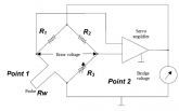
Hot Wire Anemometer
Run a current through a wire exposed to the wind and measure the temperature. The deviation in ΔT from 0 mph should be the heat removed by the wind. Nice write up on them here. The commercial ones are delicate, accurate in turbulent flow, and affected by dirt/debris (e.g., pollen) so more typically used to detect rapid air flow changes ... but an interesting concept, one might even say a hot idea.

From Wikipedia:
Several ways of implementing this exist, and hot-wire devices can be further classified as CCA (constant current anemometer), CVA (constant voltage anemometer) and CTA (constant-temperature anemometer). The voltage output from these anemometers is thus the result of some sort of circuit within the device trying to maintain the specific variable (current, voltage or temperature) constant, following Ohm's law.
Most devices uses CTA as with CCA the wire can burn up with no flow and with CVA the wire might not get hot enough with too much flow.

Additionally, PWM (pulse-width modulation) anemometers are also used, wherein the velocity is inferred by the time length of a repeating pulse of current that brings the wire up to a specified resistance and then stops until a threshold "floor" is reached, at which time the pulse is sent again.

Hot-wire anemometers, while extremely delicate, have extremely high frequency-response and fine spatial resolution compared to other measurement methods, and as such are almost universally employed for the detailed study of turbulent flows, or any flow in which rapid velocity fluctuations are of interest.

A Wheatstone bridge example; where R1 & R2 are fixed, so the bridge is balanced when R1/Rw = R2/R3.
1595162845526.png
 
...I think you misunderstood how accuracy works..,
At 10 mV you'll have a +/- 0.1 mV, at 1 mV you'll have a +/- 0.01 mV error .

That's a bit brain bending.... dang! Is this because pressure itself is logarithmic?
The datasheet of the $100 sensor says the max error is .2% FS (full scale) where FS is 3500 Pa and 1.5% of the measured value (reading).
So, you're right I was taking .2% of the full scale and applying it at the bottom.

So, the accuracy error accumulates as the voltage goes up..., that is at 0 mV when there's no wind so 0% error?
At the max reading that's the max error (.2% of 3500 Pa)?

...Send 40 kHz into one and look at another one with an oscilloscope ;)
I'm concerned that it would cost more to buy a signal generator and an o-scope than it would be replacement parts.
 
... I wonder how I can test theme to see if they even work? It would be nice to know that before building circuits designed for them....
Tested the capacitance on them, all matched the spec, but #4 was slightly off. Looks like they're not all created equally... 3 of them have green dots, 1 has a red dot (#3). I've found a few datasheets... some have different leg lengths (these are all the same length), some have green dots. My numbers match some spec sheets, but not others... and they all have same part #. Haven't found an exact datasheet that match the physical description of the these yet. But, the numbers are all within tolerances of the other numbers. Looks like the green dot is meant to be the + wire, not sure about the red dot but guessing negative positive.
 
Last edited:
Ran across a really interesting blog by a DIY builder just loaded down with hard data...updated the OP with the URL as I figure it'll be a handy spot to keep a list of interesting blogs.
 
Back
Top