diy solar

diy solar

Time for Sanity Check of the Brain Trust!

TheGriz

More Power Scottie!!!
Joined
Feb 17, 2020
Messages
128
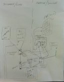
Okay folks. I am putting all the pieces together finally. Been taking baby steps as I am a novice at best, and learning tons with each step and the continued help here of the forum members. So it's time to toss my drawing out here for review, and a sanity check. But first here are a few notes of interest before you look at my drawing:

1. I am hardly an artist. Please don't laugh too hard at my art work. I have thick skin, so I am expecting some joking!
2. Because of packaging constraints, I have put the Discharge Relay on the Negative Side of the battery, as opposed to the positive side shown in the Chargery BMS8T manual.
3. I am running the positive leg of the Solar Panels through the Charge Relay. This way, when the Overvoltage Disconnect kicks in, it also disconnects the Solar Panels, thus the Panels will disconnect when the battery disconnect. I will not have the condition of the Solar Panels connected to the MPPT SCC without a battery connected.
4. This is intended to be a portable "multi-use" Solar System. I plan on using for my RV Travel Trailer. Three 100 watt flexible solar panels will be on roof of my pickup cap with suction cups (removed of course when driving). The rest of system will be in covered bed of pickup, with the RV shore cord plugged into inverter. Secondly, I am a Ham Radio Operator and will be using for outdoor events like the annual ARRL Field Day and other ham portable comms. I am also on a Search and Rescue team as a K9 unit. When not working my German Shepherd, I will be using running comms and computers when command trailer in not on scene. And lastly, I plan to use in house during power outages, within limits of course, refrigerator, internet, TV, and couple lights.

Please see attached, and let me know if I have everything lined up correctly, or if I'm going to blow myself up...LOLOL!!!

Thank you,
Mike
 

Attachments

  • 20200721_145639-1.jpg
    20200721_145639-1.jpg
    74.9 KB · Views: 16
Last edited:
Please refer to this latest attachment and disregard original attachment. I added a Master Switch off the battery pack positive to the drawing. Thanks and still looking for input on sanity on what I have laid out.
schematic.jpg
 
The MPPT's pv+ and bat+ look like they are connected?? These would be at different voltages so there is a problem.
I missed that run the battery directly to MPP for charging. You can have a breaker or a fuse between the two. The panels should be independent with their own relay. It looks like you were trying to get the battery charger on the same cutoff relay for that device you will need a third relay (AC or DC depending on where you place it.). Or put the relay between the SCC/External Charger and the battery but I do not like this approach as it shuts of the SCC if over voltage occurs to me it is still better if it reboots less often especialy if you use it to track battery state.
 
The MPPT's pv+ and bat+ look like they are connected?? These would be at different voltages so there is a problem.
Excellent pickup! Actually I noticed I have both sides of the PV on same charge relay lug as well which would do nothing to disconnect PV from SCC. So any fix???
 
I missed that run the battery directly to MPP for charging. You can have a breaker or a fuse between the two. The panels should be independent with their own relay. It looks like you were trying to get the battery charger on the same cutoff relay for that device you will need a third relay (AC or DC depending on where you place it.). Or put the relay between the SCC/External Charger and the battery but I do not like this approach as it shuts of the SCC if over voltage occurs to me it is still better if it reboots less often especialy if you use it to track battery state.
Hmmm...hence the reason I am running this past the braintrust. Thanks for input. It's back to the drawing board.
 
I would skip the relay & switch between the pv cc battery and as in other replies remove the battery charger from this side of the system.
 
Just to clarify, is this a diagram you drew yourself or did a 7-legged spider drop in some ink then scuttle to safety over your page? ;)

In addition to the points already raised, some considerations:
  1. It is good practice to be able to manually disconnect all sources of power - suggest you add an isolation switch to your array.
  2. I would recommend using busbars rather than connecting device-to-device. If you ever need to replace a component, or maybe even replace your BMS, you'll potentially end up having to re-wire everything.
  3. The circuit from battery to master switch is unprotected.
  4. The circuit from charger relay to inverter is unprotected
  5. The circuit from charger relay to fuse block is unprotected
  6. The circuit from charger relay to SCC is unprotected
  7. The circuit from charger relay to batter charger is unprotected
  8. (Not pictured) Ensure your inverter's output cannot supply your battery charger
I would recommend something like this:

chargery.png

Points to note:
  • Busbars offer convenient system additions (e.g. DC-DC converter) and easy replacements/upgrades.
  • Each circuit is fused, note the terminal fuse on the battery protecting the two busbar circuits.
  • PV circuit should be switched (not pictured)

p.s. You can buy combo-busbar-fuse units, such as this one:

2020-06-13_20-49-00.png

Edit: Added postscript
 
Just to clarify, is this a diagram you drew yourself or did a 7-legged spider drop in some ink then scuttle to safety over your page? ;)

In addition to the points already raised, some considerations:
  1. It is good practice to be able to manually disconnect all sources of power - suggest you add an isolation switch to your array.
  2. I would recommend using busbars rather than connecting device-to-device. If you ever need to replace a component, or maybe even replace your BMS, you'll potentially end up having to re-wire everything.
  3. The circuit from battery to master switch is unprotected.
  4. The circuit from charger relay to inverter is unprotected
  5. The circuit from charger relay to fuse block is unprotected
  6. The circuit from charger relay to SCC is unprotected
  7. The circuit from charger relay to batter charger is unprotected
  8. (Not pictured) Ensure your inverter's output cannot supply your battery charger
I would recommend something like this:

View attachment 18326

Points to note:
  • Busbars offer convenient system additions (e.g. DC-DC converter) and easy replacements/upgrades.
  • Each circuit is fused, note the terminal fuse on the battery protecting the two busbar circuits.
  • PV circuit should be switched (not pictured)

p.s. You can buy combo-busbar-fuse units, such as this one:

View attachment 18327

Edit: Added postscript
Thank you very much for all the suggestions. Your pic is very helpful...I can learn a lot about art work too :) Busbars were not used because of packages constraints/portability. Master fuse is in the system between the positive battery terminal and master switch...I just forgot to draw it in my pic. The PVs are also fused already but not pictured. At this point LFP cells, master switch, master fuse, shunt, two 400a DC contactors (relays) are all in a double sized Camco battery box. Will be looking at alternative packaging. Again, appreciate your and all others valuable input!!!
 

diy solar

diy solar
Back
Top