sfog
New Member
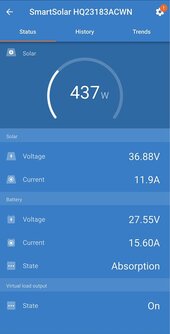
I have two Jinko 405W panels in parallel (rated Voc=50.1V, Isc=9.56A) and they are connected to a Victron 100/50 charge controller. Sunny weather (NC, US) and the panels are side by side with no shade, producing ~300W. Battery is 24V 100ah, currently in bulk charging mode.
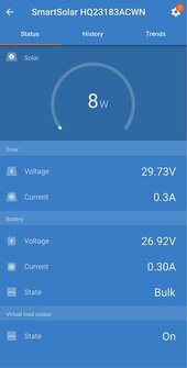
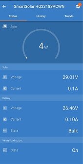
However if I connect them individually instead (directly from SCC to MC4 connector of panel) and check the smartsolar app, one them shows a very low output fluctuating around 5W or less (from screenshot with just this panel plugged in: 4W, 29.01V, 0.1A) while the other is doing all the work. Since everything up to the panel is the same, I assume the problem is specifically the panel rather than the SCC/battery or their connections. Is there anything I can do to fix this panel? Any other troubleshooting steps I can try? It was a used purchase, so my chance of refund/return is probably pretty low.
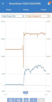
(p.s. I went back to get a screenshot for the other panel but it's partly shaded now: 75W, 41.93V, 1.8A; I added a 2nd screenshot that shows the switchover from the bad to the good panel)
However if I connect them individually instead (directly from SCC to MC4 connector of panel) and check the smartsolar app, one them shows a very low output fluctuating around 5W or less (from screenshot with just this panel plugged in: 4W, 29.01V, 0.1A) while the other is doing all the work. Since everything up to the panel is the same, I assume the problem is specifically the panel rather than the SCC/battery or their connections. Is there anything I can do to fix this panel? Any other troubleshooting steps I can try? It was a used purchase, so my chance of refund/return is probably pretty low.
(p.s. I went back to get a screenshot for the other panel but it's partly shaded now: 75W, 41.93V, 1.8A; I added a 2nd screenshot that shows the switchover from the bad to the good panel)
Attachments
Last edited: