diy solar

diy solar

Unable to deliver more than 5 amps without tripping inverter

Anthony_royalla

New Member
Joined
Jun 6, 2024
Messages
11
Location
Newcastle
My minimum goal is to deliver sustained 10 amps @240v.
My problem is that the inverter trips out at 5 amps.
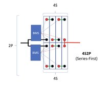
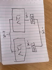
My setup is 2 x LiFePO4 batteries (banks of 4 x 304AH cels) in parallel to create one pack. Each “battery” has its own BMS. I have one 4000w inverter. I am using Smart BMS to monitor.
I have inherited this system and am unsure about some settings and aspects of configuration. I originally had a 2000w inverter and replaced that with the 4000w and the fault did not change at all (5 amp trip). My test rig is to run an induction hot plate and increase power setting whilst monitoring the current.

Before getting into the actual problem can someone advise if theoretically this system should be able to deliver the 10 amp load?
 
You need to add some info:

Specifically,you say you have 4 lithium batteries of 304 AH. this usually means they can produce 304 amp hours, but at what voltage? also, is there a C1 or C2 number which will be the maximum charge and discharge amperage in C1 = 1 hour or C2 = 2 hours?

If you are wanting to discharge to the inverter 10 amps at 240V this is 2400 watts. If your batteries are say at 53 volts, Dc, then you are asking to discharge them at the rate of 45.28 amps to produce 2400 watts at 240 volts.

Here, your 10 amps AC = 45.28 DC if batts 53 volts. So what is the max amps charge and discharge your inverter can handle from the batteries too?
Oops my bad. The 2 batteries are 12v (4 x 304AH 3.4V cells in series). 2 x 12V banks in parallel. I have set max discharge in Smart BMS to 200A per bank.
 
Just to be clear, 4 total batteries. Each outputs 12 volts. Two are in series for 24 volts. Those 24 volt strings are now connected in parallel to your inverter. So you now have 24 volts and 304AH connected in parallel making 24 volts and 608 AH. So your battery bank power is 24 x 608 = 14,592 watts. That would be 100% SOC (fully charged). 10 x 240 = 2400 watts discharge goal. At a discharge of 10 amps and 240 volts you have 6 hours of battery capacity. (Actually a little less due to an imperfect work in electricity). Your smart discharge of 200A per bank is essentially a full discharge in 90 minutes.

Please determine from your inverter's specs what the maximum charge and discharge rate of the inverter is. This is what you should set your BMS too. The batteries may charge at 200 amps per hour, but the inverter may only allow a charging of 100 amps per hour. Set BMS to inverter spec.

Lastly, there is no reason that your inverter should not be able to output the desired load of 2400 watts unless there are some surge amps (induction load startups) that are happening and causing a shutdown.

Please tell us more about what kind of loads you are running.
 
Thanks @glandpuck. I should have started with a diagram. See attached. I have 8 (304ah) LiFe PO4 cells in total. They are configured as 4 cells in series to create a 12v bank. There are 2 12v banks in parallel. Each bank has its own BMS. Across the 12v system is a 4000w 240v inverter.

Problem is that the inverter trips out when load reaches about 5 amps. Load can be anything i think, eg microwave, induction hot plate. There are no big electric motor loads so I don’t expect to see big startup currents. In any case the inverter trips out after a long time if the induction hot plate is increased slowly to 5 amps.

A related problem is that the the 2 banks do not charge or discharge evenly. One bank supplies twice the current of the other 12v bank that it is in parallel with.

I am assuming that the battery banks are unable to supply the current required by the inverter but what is the problem likely to be and how do I fault find it? Is there likely to be a bad cell?
 

Attachments

  • IMG_2212.jpeg
    IMG_2212.jpeg
    76.5 KB · Views: 5
Are the batteries balanced? How are the banks connected in parallel to the inverter?
Thanks ThaiTaffy. As I inherited this system your question prompted me to actually trace the cables and I found something weird. Look at the way the BMS are wired.
 

Attachments

  • IMG_9526.jpeg
    IMG_9526.jpeg
    123 KB · Views: 16
This is the way I think it should be wired
Correct , assume the cells with the BMS, is the 'battery'.

Having the BMS wired incorrectly may have upset cell balance, or damaged the BMS .
Suggest testing each battery with its BMS separately for charging and power delivery.

Since the previous electrical work was carried out incorrectly, there may more errors in the system, perhaps safety issues .
Screenshot_20231020-100837_Drive~2.jpg
 
Last edited:
Yes it is a 12v system. 12v is what I want on the battery side as it is installed in a boat that uses 12v.
Sorry I was thinking it was 24v as it's been suggested check each battery independently and check as much wiring as your comfortable with if the batteries have been wired incorrectly who knows what other gremlins might be hiding anything your confused take a photo and post it.
 
Wat for inverter are u using ?

My own setup a singel 150Ah lipo4 do not shutdown on a victron Phoenix 1200ve wat is rate for 850watt continu.
Even if i pull 1300watt nothing will shutdown.

So what is shutdown the bms or your inverter self.
What for wires are u using ?
On 12 volt that wire will be 50mm2 at least just to power it up.
Really is it easy use mm2.
50mm2 x4.5 on 60 celcius on 0.5meter can handel 225 amps continu.
225amps will be 2700watts of power.
To handel 4000watts you need about 100m2 kabel or 2x50mm2 kabels .

Problem if your inverter use 2 kabels on the plus connection
Both cabels need to be the same length
Or one will do more amps and come out of balance.

Some pictures will be fine so we can see it
 
Thanks ThaiTaffy. As I inherited this system your question prompted me to actually trace the cables and I found something weird. Look at the way the BMS are wired.


That seems like you have the wire from the top battery attached to the post of the bottom battery verse your inverter.

Pictures are worth a thousand words.

And I would go trace that cable again and make sure it is like this drawing then correct it if it is.
 
Wat for inverter are u using ?

My own setup a singel 150Ah lipo4 do not shutdown on a victron Phoenix 1200ve wat is rate for 850watt continu.
Even if i pull 1300watt nothing will shutdown.

So what is shutdown the bms or your inverter self.
What for wires are u using ?
On 12 volt that wire will be 50mm2 at least just to power it up.
Really is it easy use mm2.
50mm2 x4.5 on 60 celcius on 0.5meter can handel 225 amps continu.
225amps will be 2700watts of power.
To handel 4000watts you need about 100m2 kabel or 2x50mm2 kabels .

Problem if your inverter use 2 kabels on the plus connection
Both cabels need to be the same length
Or one will do more amps and come out of balance.

Some pictures will be fine so we can see it


He has a good point - you doubled the size of the inverter - were the wires already of a size good enough to carry the current or do you need to replace the wires so they can carry double the amps?


4000w /12v = 333amps

Windy nation 105c welding wire chart - you will need 4/0 cable to carry the load. This is why most say 3000w is max at 12v or more conservative 2000w for 12v and 3000w for 24v.


If you can return the inverter it probably makes the most sense to switch to 24v and put your batteries in series with an active equalizer.


1718204863191.png
 

diy solar

diy solar
Back
Top