diy solar

diy solar

Using a modified split-port BMS to drive bistable relays?

pelicanpebble

New Member
Joined
Sep 4, 2022
Messages
13
I have a 4S LiFePO4 battery bank from which I need to draw 400A for about 3-5 minutes.

After some discussion with JBD, they concluded that none of their BMS will work for me.

Hence my latest idea: Can I use a modified low-current split-port BMS to drive my charge and discharge relays? And of course the relays are bistable to make matters less straight-forward...

The basic idea is as follows:
  • Remove the charge and discharge mosfets
  • Remove the current sense resistors
  • Use the mosfet gate drive line to switch a relay-driver circuit for the bistable relays
  • Use the current sense voltage lines to connect to a new external current shunt
  • Recalibrate the BMS to the new shunt value
Basically I would take a BMS like follows:
0df1df94567245c18700ca68ab6b2cdc.svg


And modify it to look a bit like this (obviously heavily simplified):
f4b10502733745f7a5813be82271a170.svg


Could this work? Has anybody tried this?

Obviously this would not work with a single-port BMS since they always switch both mosfets after a short delay to avoid heating due to the body diode. For my idea to work, the BMS must switch e.g. the discharge mosfet only if it wants to discharge and not during charging as well...

I would welcome any comments.
 
  • Recalibrate the BMS to the new shunt value
Do you know of a BMS that allows recalibration of the shunt resistor? It seems more likely that you'll need to calibrate your shunt to the BMS

Edit: there was more to this post originally, I don't know where it went. The short version is, looks like a good plan from here. The BMS may not be able to directly drive the relays. You might need a logic level relay to drive the larger relays.
 
Do you know of a BMS that allows recalibration of the shunt resistor?
You can with JBD devices. You have to go use the JBDTool with the RS485 interface however.

It seems more likely that you'll need to calibrate your shunt to the BMS
That would probably not be feasible if I use a small BMS to modify. A device for 20A will likely have a much higher resistance as a current sense resistor than a 500A device. The first will use a higher resistance shunt to improve measurement accuracy while the latter will use a lower resistance shunt to reduce voltage drop and power dissipated in the shunt.

If I cannot recalibrate the BMS I modify, I would need to start with a large current BMS. - Which is feasible.

I am more worried about the software behaviour with regards to the discharge mosfet. Will the designers turn this on when charging to reduce voltage drop in the body diode of the discharge mosfet?

EDIT: I will need a proper relay driver circuit anyway since I am controlling bistable relays. The mosfet control lines cannot be used for this without more signal processing.

EDIT 2: When I say that JBD devices can be calibrated, I should probably mention that I have been unable to find a split-port JBD bms though...
 
Last edited:
Timely subject, I am interested in a similar approach.
Why would you not be able to work with an external shunt in parallel with the internal one?
Wonder how fast the reset time is of the current limiting circuit.
Does the bms recover from an overload current after a couple of seconds or do you have to restart?
I am using cheap 60/100amp circuit boards based on the bms chip bm3451. They have split port architecture.
I was hoping to get to a circuit where I activate the bistable relay thru a series capacitor as to limit the length of the activation/ deactivation pulse.

The bistable / latch relay I am trying is an motorhome low voltage relay with separate coils for activate / deactivate.

Johan
 
Why would you not be able to work with an external shunt in parallel with the internal one?
In theory you could connect them in parallel PROVIDED that your large external shunt has a significantly lower resistance than the internal shunt. Otherwise a much larger than designed current will flow through the internal shunt and blow them. Is safer to just disconnect them all-togther.

Wonder how fast the reset time is of the current limiting circuit.
The reset time after an overcurrent condition and an opened safety-relay? That depends on the configuration of you BMS. They typically have a parameter you set. Some are configured that the will not reset at all while a load is still connected.

I am using cheap 60/100amp circuit boards based on the bms chip bm3451. They have split port architecture.
Could you send me a link to where you bought them?

Can you test whether these boards only open the discharge mosfet for discharging or also for charging (to avoid the body-diode resistance problem)?

I was hoping to get to a circuit where I activate the bistable relay thru a series capacitor as to limit the length of the activation/ deactivation pulse.
I believe you might need a bit more electronics than that to make it work reliably. But trying cannot hurt. Let me know if this works.
 

Yeah, well removing the shunt is better but since you were talking about recalibrating the bms I figured you had not thought about changing the shunt.

And it your response you mentioned that you needed to use a large current bms in case you could not recalibrate..

So my suggestion was a small current bms with an external shunt. That is all

I do not like smart bms systems, the software seems to be to finicky and unreliable over years.. so only hardware bms systems for me.. the ones I use do not have fancy settings.

Anyhow the idea was more that if it resets very fast ,..say 1uS .... Then it could become a pwm regulator with some additional components.

Well of course more electronics is required.. since you more or less need an inverted action instead of the MOSFET opening...something needs to close to activate the latching relay..

good luck, johan
 
Yeah, well removing the shunt is better but since you were talking about recalibrating the bms I figured you had not thought about changing the shunt.
And it your response you mentioned that you needed to use a large current bms in case you could not recalibrate..
So my suggestion was a small current bms with an external shunt. That is all
Ok, I see. We got our wires crossed. Sorry.

I do not like smart bms systems, the software seems to be to finicky and unreliable over years.. so only hardware bms systems for me.. the ones I use do not have fancy settings.
I have done a bit of research on commercial devices that could help with this. None that I found are able to control bistable relays directly. But some are made specifically for controlling separate charge and discharge relays. I case you are interested I found these:

Less than 100 USD: Chargery BMS16 (without balancer, with balancer more expensive, no bluetooth, etc - BUT requires at least 13,8V to operate. For my 12V system that would require an up-converter...):

Priced at approximately 200 USD: QUCC QJ-38XS-A (also no bluetooth)

If you know of any others, I would be very interested. I do not mind smart bms as long as they have not only a bluetooth interface but also UART or RS485.

Well of course more electronics is required.. since you more or less need an inverted action instead of the MOSFET opening...something needs to close to activate the latching relay..
I was planning on an edge detection circuit. One that detects rising edges in the control line to activate the set coil with a pulse and one that the falling edge in the control line that activates the release coil with a pulse.

I am beginning to think modifying a bms is too much trouble and it might be faster to just start from scratch.
 
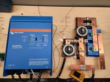
I have a 500ish amp load, this is how I did it.
Looks very solid. Could you explain a bit more?

Am I right that you use the Electrodacus as a BMS that controls relays? What type of relays do you use? Bistable or monostable?

I was considering the Electrodacus but it is no longer available; and the developer seems not to have followed through on his intention of making the design public. Otherwise I would have built one myself.
 
I just looked at the datasheet for the bm3451. I think, you have a good system to modify. It says:

[...] in the state of over-discharge [...] the output voltage of DO will turn to GND. The discharge MOSFET will be turned off and stop discharging [...].
It specifically does not say anywhere that it will turn DO back on when it detects charge current. It will charge through the discharge mosfet body diode. - Which is what we want for driving relays.

Regarding your question on the reset time on over-current:
The chip knows three different levels of overcurrent condition. They differ in the current that triggers them and the delay until they trigger. Example, 200A triggers an overcurrent fault after 2 minutes but 500 A trigger an overcurrent fault after 1 second.

Relevant to your question however is the following on page 8: The discharge overcurrent protection state will be released when disconnect the load. - So: There is no reset after an overcurrent until you disconnect your load.
 
Looks very solid. Could you explain a bit more?

Am I right that you use the Electrodacus as a BMS that controls relays? What type of relays do you use? Bistable or monostable?
Yes, I used an SBMS for the BMS. I had considered using latching or bistable relays to reduce parasitic losses but chose to go solid state instead as their consumption is miniscule (1.5ma) when on. I used a battery protects as the relay: https://www.victronenergy.com/upload/documents/Datasheet-Battery-Protect-65-A--100-A--220-A-EN.pdf The 220s are good for 600 amps for 30 seconds and 220 continuous so 2 of them should tolerate 500 amps for a few minutes at a time.

I was considering the Electrodacus but it is no longer available; and the developer seems not to have followed through on his intention of making the design public. Otherwise I would have built one myself.
This is from their website:
Due to semiconductor shortages products are out of stock until around November 2022.
For any questions use the forum: Electrodacus Forum
 
I have tried chargery on a 48 volt system and it was not accurate.. I would say stay away from chargery for 48 volt till they get their act together.. do some searches on this forum.

Noenegdod.

Very nice, do you have any separate independent breakers Incase the victron fails in an undesirable mode?

Johan
 
Noenegdod.

Very nice, do you have any separate independent breakers Incase the victron fails in an undesirable mode?

Johan
Do you mean on the 120v side? Not ATM as its not installed yet and still just building, testing and integrating several different systems before finally installing it in the truck.
 
You can easily recalibrate the shunt by adding dropper resistors on the sense lives to form a potential divider. Half the sense doubled the main current etc

The output mosfets will unlikely suit relays but you could take their gate drive signal and build an external relay driver circuit.
 
I have a 4S LiFePO4 battery bank from which I need to draw 400A for about 3-5 minutes.

After some discussion with JBD, they concluded that none of their BMS will work for me.

Hence my latest idea: Can I use a modified low-current split-port BMS to drive my charge and discharge relays? And of course the relays are bistable to make matters less straight-forward...

The basic idea is as follows:
  • Remove the charge and discharge mosfets
  • Remove the current sense resistors
  • Use the mosfet gate drive line to switch a relay-driver circuit for the bistable relays
  • Use the current sense voltage lines to connect to a new external current shunt
  • Recalibrate the BMS to the new shunt value
Basically I would take a BMS like follows:
0df1df94567245c18700ca68ab6b2cdc.svg


And modify it to look a bit like this (obviously heavily simplified):
f4b10502733745f7a5813be82271a170.svg


Could this work? Has anybody tried this?

Obviously this would not work with a single-port BMS since they always switch both mosfets after a short delay to avoid heating due to the body diode. For my idea to work, the BMS must switch e.g. the discharge mosfet only if it wants to discharge and not during charging as well...

I would welcome any comments.
The Blue Sea ML 7713 latching relay (500amps) can be driven from a 15ma signal (on = closed, off = open). No pulse required. I use it directly off an Electrodaucs BMS but others on the form use it with an Orion Jr.. Other BMSs would also work (Chargery, REC...)

 
Back
Top