diy solar

diy solar

Valence XP Super Thread

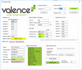
It took a while but I got capacity test info. Before starting, I charged the weak cell (2) by itself to 3.55v. After letting it relax, then set charger to 13.85 to see how all 4 cells behaved together. The first image shows this starting point. Cell 2 tended to relax lower than others; but cell diff seemed reasonable.

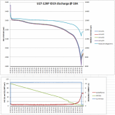
For the test, discharge current was set to 10A, and cutoff at 11v at the tester. However, the module voltage looked to be about 0.3v higher than the voltage at tester during the test (@ 10A), so cutoff at battery was more like 11.3v. Based on the voltage plot and SOC I guess it was pretty much finished at that point. Result was 110 Ah, not including 4 Ah dissipated in the wire (0.3 A over 12 hours). I don't know if it mattered that battery was never charged to 14.6v - only 13.85.
 

Attachments

  • capacity test 1 - start 1045.png
    capacity test 1 - start 1045.png
    273.6 KB · Views: 58
  • capacity test 1 - end 2230.png
    capacity test 1 - end 2230.png
    143.3 KB · Views: 58
  • capacity-test-discharge.png
    capacity-test-discharge.png
    258.5 KB · Views: 55
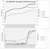
Also attaching a plot of recharge. It's kinda interesting to me that charging of cell 2 appeared to "turn off" as it diverged (lagged) from the others. It's voltage began to relax while the others continued to increase. At that point the other cells (and module voltage) ramped up similar to the rise at charge completion, so maybe it was actually fully charged even though SOC was only 70%. Before that the cell diff was really close, less than 10 mV to about 50% SOC. Based on the graph showing current the charger maybe went from CC to CV at that point, but it still seems odd that cell 2 would behave this way.
 

Attachments

  • capacity-test-recharge.png
    capacity-test-recharge.png
    257.7 KB · Views: 26
It took a while but I got capacity test info. Before starting, I charged the weak cell (2) by itself to 3.55v. After letting it relax, then set charger to 13.85 to see how all 4 cells behaved together. The first image shows this starting point. Cell 2 tended to relax lower than others; but cell diff seemed reasonable.

For the test, discharge current was set to 10A, and cutoff at 11v at the tester. However, the module voltage looked to be about 0.3v higher than the voltage at tester during the test (@ 10A), so cutoff at battery was more like 11.3v. Based on the voltage plot and SOC I guess it was pretty much finished at that point. Result was 110 Ah, not including 4 Ah dissipated in the wire (0.3 A over 12 hours). I don't know if it mattered that battery was never charged to 14.6v - only 13.85.

That's a pretty bad capacity compared to all the ones I've tested which were still holding somewhere between 96 and 100% but none of mine have had any possible damage with over or under voltage conditions in the past.
one thing you want to make sure of if you're using the built-in batteries amp meter to make sure it's accurate. Disconnect all wires from the battery and check the software for the amperage. If you see amperage moving then of course you're going to get an inaccurate amp hour capacity. About 10% of my batteries have inaccurate amp meters. some of them showed their discharging at nearly two amps when in fact there's nothing drawing power from or giving power to the battery and the voltage remains stable even as the percentage of charge continues to fall.
 
Aloha. Still waiting on my batteries that I purchased from Travis who also was kind enough to turn me on to this forum thread.

In the meantime I’ve been researching solutions for how to go about monitoring my bank on my solar electric catamaran.

I have been in communication with Thunderstruck which has been mentioned here. They make an aftermarket BMS for the XP batteries. I also turned them on to the thread as well.

In my communication to them, I was trying to determine if their product activates the internal boards in the XP batteries enabling the built in under over charge protection. I had hoped that since their BMS provides 5V and is in communication with the batteries and able to get individual cell voltages in order to trigger external relays based on over under set values, that it also activated internal balancing feature of the batteries.

Unfortunately I don’t believe that they do as they have not verified if it does, and it is unlikely that it would based on the info here in the thread and the challenge many of you have had cracking the code to activate this feature.

Product development is currently on hold, but I suggested that this was a feature a lot of hobbyists would like to take advantage of. If their product could activate the built in over/under charge protection as well as balance between batteries in a series bank (a feature that is already planned), that those key features along with the features the unit already provides (setting a high and low value, monitoring each cell, and triggering an external relay for disconnect of loads or charging if threshold values are exceeded) that they would have a very usable product.

I may end up purchasing one for the time being and integrate it with my Victron MPPT chargers so that the Thunderstruck BMS’s open collector high output triggers a disconnect of the charger if a set voltage is exceeded. Certainly that is better than nothing at all. Eventually I would like the added first stage protection of the built in over under and balancing features as well.

Which brings me to this listing which just appeared on Ebay. I don’t know if anyone has seen these or has any first hand experience with them, but from what I can tell they will activate the built in boards and enable intra and inter charging and balancing.


Also, I spoke with my Dad (electronic engineer) about the challenges of monitoring and managing these batteries, and he basically said it would be about $10K to design and engineer a BMS that does what the Valence BMS does along with the ability to trigger external relays to shut off load output or charging input if a problem arises.

Thunderstruck certainly already has a head start on this. I’m hopeful they might seriously consider figuring out how to activate the internal safety features of the XP’s and add that features to their BMS product.

The XP series of batteries does not have the ability to disconnect its output. If you open one up you'll see that the individual cell blocks are hardwired to the output and there's no switch or mosfets inside in order to interrupt their power output. They report cell voltages to & rely solely on an external device uBMS to open the external contactor relay.

The BMS on eBay or a few like it has been purchased by at least two people here on this thread. So far they haven't got it working. the first guy literally brought it to me and we played with it for a while and determined it was fried because they're pinout diagram was incorrect.

The other guy has not had time to fully test its abilities and so far has tried to but not had any success at connecting to it with the valence BMS programming software. So it appears it needs an actual Texas instruments chip programmer in order to flash different battery configurations to it. It's lack of compatibility with valance makes him worried that it won't do both balancing techniques with the XP batteries like we need.

Am I wrong to assume the thunderstruck will enable the internal board to balance its own cells? It's pretty simple to verify if a resistor is getting warm or not just by touching it with your finger so anyone who has a thunderstruck could test this for us. also I'm fairly certain if a thunderstruck causes the green light to flash every 5 seconds instead of 20 that would indicate that the internal balancer is active. there are other people who have definitely activated this internal balancing ability very easily and say it's a simple wake up command over the rs-485 to the battery. I'm absolutely positive the thunderstruck unit has all the hardware necessary to accomplish this.
 
Thanks for the info on that Ebay BMS Travis. I had a feeling it might be the one discussed earlier in the thread.

Thunderstruck did not design their BMS to specifically do anything more than measure individual cell voltages so that an over or under condition would trigger an external relay.

When asked if they knew if the internal balancing was activated when their unit was in communication, supplying 5V and a charge voltage of 13.8+ applied, the response was that they could not confirm this and would have to test it.

In the manual it states that future software/firmware updates will include the ability to balance between batteries within bank, although no word yet on when that might be.

When I mentioned a disconnect, I was referring to using the relay trigger of ThunderStruck’s BMS to activate the disconnect feature of my MPPT controllers. That way if the Thunderstruck determines a cell is over its high limit, it can turn off my charging. The same could be done for loads of course to avoid a undercharge state.

Me, I’m more concerned about leaving my boat in the water for periods of time and not having a meltdown due to a cell imbalance issue.

On that note, interestingly the Thunderstruck guys said that they have a number of boat customers using the XP’s in small series systems (24/36/48) without individual cell monitoring or safety features and no one has had any issues. They feel the XP’s tend to stay pretty well balanced provided you don’t run them down and program your chargers correctly.

Here’s some of the info from our communications:


We originally believed that since our BMS is communicating with the modules and is providing 5 volts to them, that the balance process in each module would activate.

However, we have not verified this, so I have to say "I don't know" as an answer to your question.
We are in the process of verifying this, however it is not a trivial test.


Early versions of BMSs sometimes utilized "passive" balancing which happened by charging shallow cycles until one cell hit it's high voltage limit. The voltage would then drop and you could charge again. Over time and cycles this brought the lower cells up. With such a relatively low number of cells, it can be more important to monitor the low voltage limit than to balance between them but I believe you are correct otherwise.


I agree with Michael. Also, in our experience with the Valence modules over several years, the cells do not tend to get unbalanced unless something is wrong with one of the cells. In the case that one cell is weaker than others, the internal balancing current is so low that it would not help a weak cell. This is why we designed a simple BMS to handle the voltage limits as the main function. It is a cell health and safety issue we are covering, and this has been adequate in our estimation
 
Thanks for the info on that Ebay BMS Travis. I had a feeling it might be the one discussed earlier in the thread.

Thunderstruck did not design their BMS to specifically do anything more than measure individual cell voltages so that an over or under condition would trigger an external relay.

When asked if they knew if the internal balancing was activated when their unit was in communication, supplying 5V and a charge voltage of 13.8+ applied, the response was that they could not confirm this and would have to test it.

In the manual it states that future software/firmware updates will include the ability to balance between batteries within bank, although no word yet on when that might be.

When I mentioned a disconnect, I was referring to using the relay trigger of ThunderStruck’s BMS to activate the disconnect feature of my MPPT controllers. That way if the Thunderstruck determines a cell is over its high limit, it can turn off my charging. The same could be done for loads of course to avoid a undercharge state.

Me, I’m more concerned about leaving my boat in the water for periods of time and not having a meltdown due to a cell imbalance issue.

On that note, interestingly the Thunderstruck guys said that they have a number of boat customers using the XP’s in small series systems (24/36/48) without individual cell monitoring or safety features and no one has had any issues. They feel the XP’s tend to stay pretty well balanced provided you don’t run them down and program your chargers correctly.

Here’s some of the info from our communications:

I have Several batteries that weren't balanced in a year or two & have one cell bank that was 20 amp hours behind. That's a considerable amount. Thats makes that cell bank about 16% state of charge behind. And if you never balance that will only grow. I assume around 10% per year. That would be pretty stupid to have a 30 year battery only capable of 50% capacity after 5 years so balancing is a must with batteries this old. The same batteries have been very easy to maintain balance once they were initially brought to a balanced state.

I would love for somebody with a thunderstruck to test it's balancing abilities for us. It's a very easy test. The test would work like this, charge the battery to 13.8 and then take the side cover off and apply 3.75 volts to one of the cells while leaving the balance connector in place and plugged in. The resistor should get warm to the touch. It's quick and easy test I've done it several times. Also make note whether the thunderstruck causes the green light to blink every five second.

Does anybody listening have a thunderstruck and want to do this test for us? PM me and I'll help you. That would be awesome thanks.
 
I have one on the way Travis and will be happy to test.

If it doesn’t do it currently, I have made them aware that it would be a great feature to add.

I needed a way to monitor the individuals cells as we discussed, and wanted the ability to disconnect my chargers if a problem occurs, so I decided even if the Thunderstruck BMS doesn’t enable balancing at this time, it was still the best option for me for monitoring I individual cells and triggering a disconnect.

I’ll be in touch.

Thanks!
I would hate to have to add one of these $10 balancers to a thunderstruck set up.

 
Maybe thunderstruck could add a temperature monitor to also disconnect the contactor if needed? Or we could jerry-rigg our own temperature protection circuit in with the thunderstruck in order to break the 12 volt Supply that goes to the relay and keeps it closed. There's probably a large number of thermostat style controllers that could break this connection.

 
This may be a stupid question, but are we not able to just splice in a external bms that you would use on a diy LFP battery system like the overkill bms Will recommends? And not have to try and hack or communicate with the internal valence system?

And would the epever SCC not control the temperature protection?
The AN model says this: "Battery Overheating The controller can detect the battery temperature through an external temperature sensor. The controller stops working when its temperature exceeds 65 °C and begins working when its temperature is below 55 °C. Lithium Battery Low Temperature When the temperature detected by the optional temperature sensor is lower than the Low Temperature Protection Threshold(LTPT), the controller will stop charging and discharging automatically. When the detected temperature is higher than the LTPT, the controller will be working automatically (The LTPT is 0 °C by default and can be set within the range of 10 ~ -40 °C)."

and the BN manual states: " Battery Overheating The controller detect the battery temperature through the external temperature sensor. If the battery temperature exceeds 65ºC, the controller will automatically start the overheating protection to stop working and recover below 50 ºC."

Again excuse me if this has a blatant answer that im not seeing, im very new to solar and even newer to figuring out how to use these batteries. Just for reference in my situation I would be using 2 in parallel in a van that will be in different climates occasionally.
 
I have one on the way Travis and will be happy to test.

If it doesn’t do it currently, I have made them aware that it would be a great feature to add.

I needed a way to monitor the individuals cells as we discussed, and wanted the ability to disconnect my chargers if a problem occurs, so I decided even if the Thunderstruck BMS doesn’t enable balancing at this time, it was still the best option for me for monitoring I individual cells and triggering a disconnect.

I’ll be in touch.

Thanks!
Why not just use one of the high voltage Valence BMS? Travis got me one with a simple step-up to supply the higher voltage and it's working like a dream.
 
Why not just use one of the high voltage Valence BMS? Travis got me one with a simple step-up to supply the higher voltage and it's working like a dream.
I had a deal one one on ebay but missed out on it being not sure if it would work plug n play. It seems that some have not been able to get the bms to work with out re flashing it to the specific configuration it is being used on. Any other ones I have seen are extremely expensive.
 
Both Temperature and Inter-balancing are features that Thunderstruck has stated are slated for future development.

The big question is, does their product in it current configuration enable Intra-balancing?

With Travis’s knowledge and help, we will try to figure that out once I get my hands on the batteries and BMS.

As for using the Valence BMS, I need something that is small that can live in a Marine environment with the ability to “set and forget” -a little black box if you will. I don’t want to be using a device or software on the water. My boat stays in the water for months at a time and I’m mostly concerned about a high voltage cell imbalance issue during daily charge cycles and would like the ability to disconnect the chargers in the case of a problem. If I find the chargers disconnected, I will then troubleshoot the issue (connect a device) and determine what actions to take.

My charging system is built around Victron products. I use two of their MPPT Bluetooth chargers paired with their BMV-712 and a shunt. All are networked together. Fortunately the chargers have the ability to assign their VeDirect ports to act as a remote on/off switch. Using the Thunderstruck HV and LV trigger outputs, I can trigger the chargers to shut off if/when a particular cell hits a Voltage High Limit without the need for a separate relay acting as a hard disconnect.

Since I use a master battery disconnect switch for all loads, the boat only has input power when left unattended. When in use, I mostly run off sun power and drain the bank very little, so I don’t need to worry so much about a Low Voltage trigger.
 
My charging system is built around Victron products. I use two of their MPPT Bluetooth chargers paired with their BMV-712 and a shunt. All are networked together. Fortunately the chargers have the ability to assign their VeDirect ports to act as a remote on/off switch. Using the Thunderstruck HV and LV trigger outputs, I can trigger the chargers to shut off if/when a particular cell hits a Voltage High Limit without the need for a separate relay acting as a hard disconnect.

So the Victron charger alone will not disconnect the battery in a high or low voltage situation? Or is it that it will do that but not for each individual cell only as the battery as a whole, which could result in them becoming un-balanced correct?
 
Correct, mostly.

The Victron charges have the ability to turn off charging (input power) to your bank by way of setting a V threshold. It also has a bunch of features where once the V drops it will reconnect and continue to try to over a period of time or a set time.

It does this by monitoring overall voltage, not individual cell voltage.

The Thunderstruck BMS has the ability to monitor individual cells and then trigger an external relay for a hard disconnect, or a device like my chargers that can be triggered to turn off.

As for disconnecting loads, the smaller ones have dedicated Load Output terminals. All loads powered by these terminals can be controlled in a number of ways like disconnecting if a low or high V threshold is passed, or turning all loads on or off on a set schedule, sounding an alarm or triggering a relay, or turning them off or on remotely with a device running the App, etc..

So, in order for output power to be disconnected all loads must go through the charger.

My electric motors pull more Amps than my chargers can provide through the Load Output terminals, so they are wired directly to my bank through a master battery switch. Then my lights, USB charging, etc.. get powered by the Load Outputs allowing me to do things like turn on/off my lights off remotely using my IPhone.

Victron also makes a Battery Protect product that you can wire between your battery and loads that will hard disconnect if a high or low V is met and reconnect when certain parameters are met. The only problem for some is it is a one way device. So for example, you can’t have charge current running in the other direction.
It can also be used on the input side between a charger to disconnect input power to the bank.
 
Last edited:
Ok so I would be protected other than intra cell balancing with a good charge controller which will monitor mainly HV going into the battery and cut off solar charging if high also will monitor temperature. And a battery protect after battery for Low voltage that is for if I forgot to watch my voltage and power is still being pulled. Also having manual disconnects before and after battery for emergency/working on situations. And I can connect the batteries to my computer once a month and check individual cell balance. Right?
 
Last edited:
Ok so I would be protected other than intra cell balancing with a good charge controller which will monitor mainly HV going into the battery and cut off solar charging if high also will monitor temperature. And a battery protect after battery for Low voltage that is I forgot to watch my voltage and power is still being pulled. Also having manual disconnects before and after battery for emergency/working on situations. And I can connect the batteries to my computer once a month and check individual cell balance. Right?

Without knowing exactly what your system is and what it is designed to do, it sounds like you should have your bases covered with a setup like that.

One thing to keep in mind is the Bluetooth line of Victron MPPT’s have the ability to enable and disable the charger from within the App, so if you need to work on something downstream you can turn them off.

And I believe the Battery Protect has the ability to wire a manual switch to control on/off to loads.

So between the two, MPPT on the input side to disconnect if over voltage and Battery Protect on the output side if under, you should be able to turn everything on and off to do work or troubleshoot.

If you added a BMV712 with a shunt and a temp sensor, you could monitor overall temp at the battery and set thresholds to trigger a disconnect. The MPPT has a built in temp sensor for basic monitoring and adjusting of charging which won’t help much if it’s not located near batteries. And Victron also makes a Smart Sense product that would report temp at the battery to the App that you could then network with the charger. This might be a better option since you are parallel and would need individual readings, although I’m not sure if it will provide the same disconnect features as the BMV712 with shunt.
 
Last edited:
Yea its just 400w solar van build and nothing crazy like electric water heater or induction stove tops. Biggest power draw will probably be my regular dorm fridge from inverter and a computer battery. Everything 12v wish I could do 24v but it seems like it complicates things using these batteries.
 
This may be a stupid question, but are we not able to just splice in a external bms that you would use on a diy LFP battery system like the overkill bms Will recommends? And not have to try and hack or communicate with the internal valence system?

And would the epever SCC not control the temperature protection?


Again excuse me if this has a blatant answer that im not seeing, im very new to solar and even newer to figuring out how to use these batteries. Just for reference in my situation I would be using 2 in parallel in a van that will be in different climates occasionally.

from the sounds of the way your charge controller is low temperature protection circuit works it should stop charging when below freezing so that would work. And I wouldn't worry about overtemperature cuz you're probably not pushing enough amperage to even worry about that.

and you asked if you could hook up a cheap simple cell balancer splicing it in? Yes you can do that you could even spice it in so that both the original BMS was still present end able at the same time as a cheap cell balancer like this one. https://www.ebay.com/itm/Li-ion-Lif...726328?hash=item2ae496faf8:g:J5UAAOSw5IZeeLM3

And then of course yes you could have a regular valence brand BMS and you're right to worry about the flashing but if you get one from me no need to worry cuz I can do that.

I think for you it's more about the overall cost and the valence BMS is more expensive. In your situation with some splicing work the super cheap cell balancer add-on I posted above is probably your cheapest option. if you went the cheapest route like this the only thing left to worry about is under voltage. Will you accidentally leave the 12v dome light on? You know anything that's 12 volts and connected directly to the battery can continue to pull the voltage down indefinitely. Anything else that's connected to the inverter will obviously stop pulling power when the inverter does its low voltage shutdown. with these batteries anything below 12 volts is basically dead but they can go clear down to 10.5 or 11 or something quite safely. The exact low voltage thresholds are all in the manual.

the reason I bring up dead below 12 volts is that if you have a customizable low voltage cutoff you could easily set it for 11.5 volts and you're going to get to use most 99% of the power of available when you cut it off at that voltage which is a much safer voltage to cut it off at compared to the absolute low safe mark mentioned in the manual.
 
Back
Top