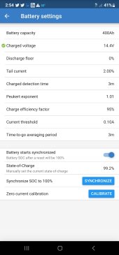
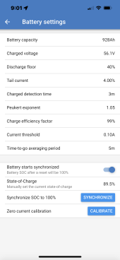
The Peukert exponent is the discharge efficiency fudge factor. See Victron's explanation document attached. Charge efficiency is ....charging current efficiency.
LFP batteries are very efficient for charging and discharging. It will be between 99.5% at discharge less than 0.1 C(A) current, and about 97% at 0.5 C(A) current. That chart attached has efficiency vs current so use a number that matches your average use case current draw for discharge and charge currents.
Your Peukert setting is likely a little low, meaning too good efficiency.
Your Charge efficiency is also likely too low, meaning too poor. Probably want 97% to 98%.
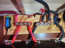
Problem is 12v systems often have a lot of cable losses so getting the number right is tougher.
What all this means is the fudging factor the Columb counter applies to battery input current (charging) and battery output current (discharging) per second of time to cumulate the goes-into minus the goes-out-of battery AH's of current.
The cumulative Columb counter tally is like 'dead reckoning' navigation. Errors are accumulated over time due primarily to current measurement accuracy of shunt depending on absolute current. Low currents usually have poorer accuracy.
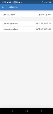
The full battery 100% reset is a reference point when battery is fully charged up that resets the Columb counter and clears out any accumulated errors that have grown over time. 2% tail current is likely too low and restrictive for resetting to 100% full charge. It may cause it to reset less often resulting in more accumulated errors due to longer periods between resetting to 100% full status.
For Columb counter to work it needs two references. 1) battery AH capacity. 2) A fully charged 100% or known state of charge to start working from.
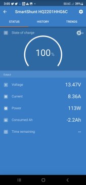
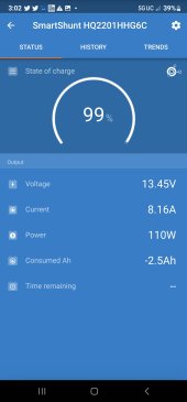
There are provisions to estimate SoC when first installed and manually setting SoC into battery monitor so you can get a close number right after installing unit. Best to fully charge battery and make sure monitor resets to 100%. If it does not reset to 100% when you think you fully charged battery, then you have the 100% full trigger set to restrictive. This is usually done when just slightly below absorb voltage but Victron also adds the taper down tail current during absorb charge period to declare a full charge.
For 'smart' monitors, they can figure AH on their own but require a full charge, full discharge cycle to do so. You can manually put in any number you like for battery AH capacity. For example, you might want to set it to 80% of actual battery capacity if you want the display to be conservative, holding 20% in reserve from view so you never get a low battery BMS shutdown when monitor still shows 10% capacity left.
When you have normal inverter/charger operation with random charging and discharging you may never hit the low tail current number and therefore never reset the Columb counter to clear cumulative errors. I would use a tail current, relative to battery AH entered, of about 20-40% of your typically bulk charging current.
View attachment 129726