diy solar

diy solar

Victron shunt installation

Jazlovesaproject

New Member
Joined
Apr 17, 2024
Messages
14
Location
Devon, England
Hi Guys, just about to install my victron shunt and temp sensor. Wanted to clarify a few things first.

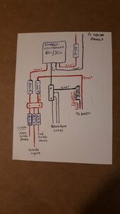
Does my diagram look like I know what I am doing?
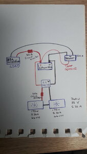
20240522_134804.jpg

Best way to switch off solar? I'm going to fit a circuit breaker between panels and charge controller for future use but for now am I best off covering panels and disconnecting the mc4 connectors on the roof?

Presumably the positive and negative to my battery from the charge controller stay on the battery first and I fit the negative from the shunt onto the battery on top of charge controller cables?

The other negative on the shunt I connect the negative from my load.

And the temp sensor is going onto the positive battery terminal.

I've used 6mm2 cable from panels to controller and then from controller to battery. Presumably this would be alright to use when connecting the shunt?

(I've used a 10mm2 cable for my load, but that's not because of the amps but rather the distance I'm travelling, and trying to avoid voltage drop)

Just for some back ground I'm using the solar to power 12v lighting and charging throughout my house. So far I've only installed about 10A worth in the house so trying to crack on with that as battery not discharging enough to check panels working efficiently. But also without shunt totally paranoid about over use, hopefully the insight the shunt will give me will help me determine what part of the solar system can be improved to maintain power over winter months.

Thanks for any help or suggestions you can give :)
 
Does my diagram look like I know what I am doing?
Negative ;)

The shunt needs to be connected between the battery negative _before_ both charge and load connections. It needs to know what charge is going into the battery as well as what is drawn from it.
 
I've used 6mm2 cable from panels to controller and then from controller to battery. Presumably this would be alright to use when connecting the shunt?
Technically OK, but personally, I'd put in larger cable to handle the potential 40A load at 12V.

And you should have a fuse between the charge controller and battery pack.
 
Technically OK, but personally, I'd put in larger cable to handle the potential 40A load at 12V.

And you should have a fuse between the charge controller and battery pack.
Thanks for your help! Right this is really helpful, currently I do have a 40A circuit breaker between my charge controller and battery, but I was going to move it when I installed the shunt to the solar positive between panel and charge controller. This is because I thought if the breaker broke the connection between controller and battery it would fry the charge controller? But that's wrong? Should I have both or not bother with one between panels and controller?
 
No. The shunt requires a positive, fused connection power lead (supplied with the shunt) that connects to the battery terminal.
Ah ok, I thought if I was using the temp sensor then I was putting that instead of the supplied power lead. The temp sensor has two pin connectors that go into the shunt where the positive red wire(s) would go if I didn't have the sensor. I thought it was a one or the other deal?
 
Negative ;)

The shunt needs to be connected between the battery negative _before_ both charge and load connections. It needs to know what charge is going into the battery as well as what is drawn from it.
Sorry for being dense, do I put the shunt onto the battery terminal and then the charge controller. Or do I do a negative busbar and put only the shunt onto battery and put the solar onto the busbar?
 
Sorry for being dense, do I put the shunt onto the battery terminal and then the charge controller. Or do I do a negative busbar and put only the shunt onto battery and put the solar onto the busbar?

All the info you need is in the pdf; see

The diagram on page 21 probably most closely matches your proposed installation showing location of the SS, fuse and shunt power / temp sensor if you have one.
 
Do you still suggest I keep a fuse between charge controller and battery?
Fuses are needed to protect the wires from too much current being passed in a fault condition; so between battery and charge controller, yes I do.

A fuse is not needed between a single PV panel string and the CC as the panels won't be able to deliver more current than their Isc rating.
 
Fuses are needed to protect the wires from too much current being passed in a fault condition; so between battery and charge controller, yes I do.

A fuse is not needed between a single PV panel string and the CC as the panels won't be able to deliver more current than their Isc rating.
Thanks for the help. I think I've got my head around it now. Does this look better?
20240524_212633_001.jpg
 
Or do I do a negative busbar and put only the shunt onto battery and put the solar onto the busbar?
Yes, as in your latest diagram. The 100A main fuse should be as near as practical to the battery positive.
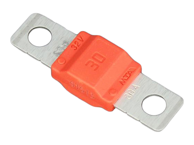
To withstand the possible high fault current a link fuse is unsuitable.
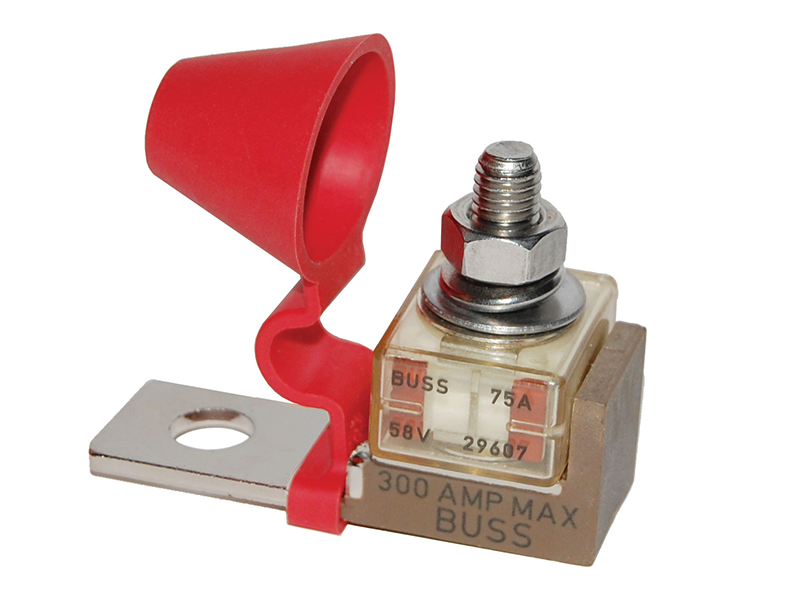
Recomended a mrbf fuse and holder directly on the battery positive, or as near as possible.


Screenshot_20240525-153754_Drive~2.jpg

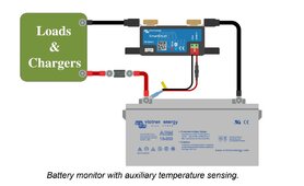
Temp sensor is a dual lead device, connect as shown. Set up the VE bus so the smart shunt can report battery voltage and temperature over Bluetooth to the MPPT controller.
 
Yes, as in your latest diagram. The 100A main fuse should be as near as practical to the battery positive.
To withstand the possible high fault current a link fuse is unsuitable.
Recomended a mrbf fuse and holder directly on the battery positive, or as near as possible.


View attachment 217532

Temp sensor is a dual lead device, connect as shown. Set up the VE bus so the smart shunt can report battery voltage and temperature over Bluetooth to the MPPT controller.
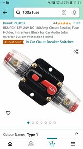
Mike, thanks so much. Great to know I'm getting closer to right. I've already purchased the circuit breakers but if I've got the wrong thing I can defo order something else. This is what I've got.. (I've used this type for throughout the whole system so far and that what's I've got in the diagram)Screenshot_20240527-111126_Amazon Shopping.jpg
 
This is what I've got..
Those inline breakers , ( and similar inline fuse holders), intended for car audio, are dangerous, overheat and melt.
It's difficult to get safe reliable circuit breakers in the UK, almost all the units on Amazon and eBay are poor quality.

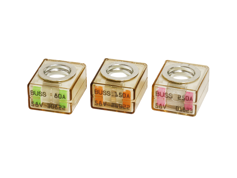
Over 30 amps use midi or mega link fuses in holders, with eye terminations crimped onto the cable. Unless its the main battery protection fuse, where MRBF for a 12v system, and Class T (HRC) for 24 to 48 volt system.


With wire terminations, apart from terminals designed for multi strand cable, ( as on Victron units), its reconended to use crimped eye terminations on the cable.

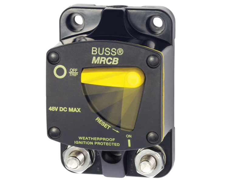
If a breaker is a must requirement, then
because I thought if the breaker broke the connection between controller and battery it would fry the charge controller?

a reliable brand is Bussmann/ Bluesea, ( but expensive), example,

For the solar panels, two in series or parallel don't need over current protection, (only 3 or more in parallel). However a useful item is an isolator switch on the solar panel feed, ( must be designed for solar and may incorporate a MCB)

Two solar panels, 44v OC are near the limit of a 100 volt MPPT where you consider the cold weather increase of the open circuit temperature. Below 25C the voltage will increase around 0.4% for every 1 deg C below 25.
Thus with the two in series you could exceed the 100v ( hard) limit if the temperature drops below -5C.

broke the connection between controller and battery it would fry the charge controller?
If you are using a 100 30 Victron controller , its internally protected against loosing a connection to the battery.

I think I understand why you are building this system but be aware in Devon, ( I live there when I am in the UK), over the winter there will be days, sometimes weeks, where solar yield will be low. Idealy you need to consider alternative power source.
 
Hi Mike, thanks again!
Hah, sounds like I'm getting lots of stuff wrong. I'd seen alot of those type breakers on YouTube videos so thought they would be sufficient. I can return some of them so will do that and replace with the 30A+ link fellas you suggest. The mrfp aswell.

Trouble is I'm a complete beginner and other than this group and relying on info from sale people over the phone I have no guidance. I go to YouTube with a question and end up with 5 new ones. I'm sorry that I seem, infact am, so dense.

I was recommended the victron smart controller 100v/30 when I gave the specific info about my panels (over the phone to online seller) so unsure as to why it's not gonna cut it, frustrating. Can I just keep an eye on temperature and disconnect if going into the minus's? I can't afford to replace controller now.
If so then isolator switch gonna be useful for that.
Or would my other option be to run them in parallel instead? Thereby (as I think I understand it) lowering the voltage?
Would the knock on effect of that be slower charging of the battery?

Literally so sorry if I'm getting this wrong, please stick with me!

I'm in a very bad position, from a solar point of view, I live in a valley full of trees. Solar has always been a dream and now the kids are at school I get a bit of life back. That's what this is for me. I've accepted I might not generate during the winter. That being said I was hoping I might be able to upgrade more in the future and do so. All I'm planning at the moment is 5v charging and led lighting. Lighting being the priority if charge is low. At the moment I've got my kids bedroom drawing max 8 amps, and the battery has recharged everyday before the sun is even on the panels. So from my point of view, it's going great, when a few weeks ago it was all a foreign language and I had nothing.
It's great to have the info on the breakers/fuses, I wish I'd known that sooner. Thank you :)
 
Recommended the victron smart controller 100v/30
The 100 30 controller is OK for your application. All you need to do is to wire the panels in parallel, the battery will still be charged OK. Under partially shaded conditions parallel connected panels out perform series panels, although any significant shade will reduce panel output. With the smart controller you have useful information via the Victron app on the solar power produced.

It sounds like your 12v loads are relatively small, a few amps. Where you have a led light unit, or led strip, taking a few amps and connectecd by, for example, 1mm2 cable, this needs a suitable fuse. 1mm2 cable is rated at 16 amps maximum, but the internal wiring in the led light/strip may be smaller gauge. Thus if the light is taking 3 amps then fuse at 5 amps.
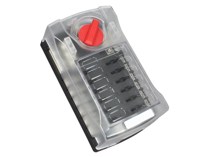
A useful distribution fusebox for small appliances and led lights is, ( 6 or 12 Way).


Connect this to the main busbars via a 40 amp fuse and 6mm2 cable . Connect your lights and 5v chargers to this fuse box. Idealy each circuit should be independently fused.

Perhaps if you sketch out you proposed12v distribution system I could comment.
 
Back
Top