diy solar

diy solar

Voltage difference between Victron charge controller and BMS

zerzuri

New Member
Joined
Nov 16, 2019
Messages
36
Hi
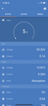
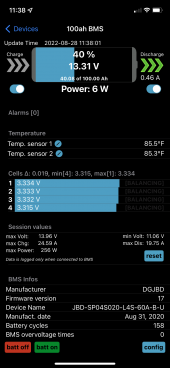
I am a newbie to Solar. I have a 100ah sinopoly LifePo4 battery pack and 80ah LifePo4 battery pack connected in parallel. The voltage of the two parallel packs shows 13.3v where as Victron charge controller sees the two pack’s voltage as 13.81. Since the charge controller sees a higher voltage it goes to absorption mode where the two packs clearly are not charged fully. I was wondering what May be the reason of this voltage difference and how can I solve this problem.

Thanks for your comments and guidance in advance.

Oz
 

Attachments

  • F67232E7-94CC-49BB-82F9-F979F4A7BC40.png
    F67232E7-94CC-49BB-82F9-F979F4A7BC40.png
    268.7 KB · Views: 5
  • C276F003-B40C-4763-BC2B-35FC5F14E5FF.png
    C276F003-B40C-4763-BC2B-35FC5F14E5FF.png
    519.4 KB · Views: 5
First off, I would recommend doing some studies on how to do voltage drop tests. It's where you place a voltmeter + and - leads in series, around an area of the circuit (like at two points where there is a cable, or a fuse holder, or something you want to test for loss, in that section between), in order to isolate a voltage differential between the beginning and the end of a point (indicating the amount of voltage drop being introduced in within that section of the circuit).

If you can go around the circuit all the way (both positive and negative sections of the circuit, find all the voltage drops, they should all add up to amount to your complete voltage drop seen across the whole circuit.

Work at finding where the deficiencies are (areas adding the most voltage drop) and correcting or improving all the voltage drops to help lower the overall circuit voltage drop being seen. Maybe larger cables, fixing bad connection points, optimizing component conductor materials (like bus bars, fuseholders, etc).


Then, I personally would recommend (me coming from Victron ecosystem myself), to get a BMV-712 battery monitor which will provide a voltage, current, and temperature measurement point right at the shunt they have you install (close to the battery), where the charger can read from remotely (via bluetooth or VE.Direct network connection).

Once installed, you go into the Victron Connect app, create a Group, add both the BMV-712 and your Victron Charge Controller to the group, and then the charge controller will read voltage from the shunt instead of itself.

So that also helps reduce the differential between what the charger would perceive as the voltage, since it would see voltage being sampled from the shunt, which would be mounted close to the battery bank.

That's how I would probably tackle the situation (well, that's how I use my system now, except I have 2 charge controllers in that network group, so they both read from that shunt and stay in charge cycle sync with each other).

I don't know if you have the Blue Solar or the Smart Solar, I have the latter, and they have a bluetooth module built right into them, so they connect seamlessly to the BMV-712 without having to buy the external Victron bluetooth module or anything (so I don't need a cabled VE.Direct connection there).
 
Last edited:
There is only a small current flowing so volt drops due to resistance can be neglected.
With the cell readings and battery SOC, the BMS voltage of 13.3 would seemto be correct.
It would be useful to check with a meter, measure at the battery and at the controller.
By a process of trial and error you shoud be able to solve the problem.
Start by separating the batteries and charging each separately to full, ideally with an AC based charger.
Connect the controller to a single battery, even a car starter battery, and confirm the voltage reading is correct.

Mike
 
First off, I would recommend doing some studies on how to do voltage drop tests. It's where you place a voltmeter + and - leads in series, around an area of the circuit (like at two points where there is a cable, or a fuse holder, or something you want to test for loss, in that section between), in order to isolate a voltage differential between the beginning and the end of a point (indicating the amount of voltage drop being introduced in within that section of the circuit).

If you can go around the circuit all the way (both positive and negative sections of the circuit, find all the voltage drops, they should all add up to amount to your complete voltage drop seen across the whole circuit.

Work at finding where the deficiencies are (areas adding the most voltage drop) and correcting or improving all the voltage drops to help lower the overall circuit voltage drop being seen. Maybe larger cables, fixing bad connection points, optimizing component conductor materials (like bus bars, fuseholders, etc).


Then, I personally would recommend (me coming from Victron ecosystem myself), to get a BMV-712 battery monitor which will provide a voltage, current, and temperature measurement point right at the shunt they have you install (close to the battery), where the charger can read from remotely (via bluetooth or VE.Direct network connection).

Once installed, you go into the Victron Connect app, create a Group, add both the BMV-712 and your Victron Charge Controller to the group, and then the charge controller will read voltage from the shunt instead of itself.

So that also helps reduce the differential between what the charger would perceive as the voltage, since it would see voltage being sampled from the shunt, which would be mounted close to the battery bank.

That's how I would probably tackle the situation (well, that's how I use my system now, except I have 2 charge controllers in that network group, so they both read from that shunt and stay in charge cycle sync with each other).

I don't know if you have the Blue Solar or the Smart Solar, I have the latter, and they have a bluetooth module built right into them, so they connect seamlessly to the BMV-712 without having to buy the external Victron bluetooth module or anything (so I don't need a cabled VE.Direct connection there).
Thanks for your response. I will try it.
 
There is only a small current flowing so volt drops due to resistance can be neglected.
With the cell readings and battery SOC, the BMS voltage of 13.3 would seemto be correct.
It would be useful to check with a meter, measure at the battery and at the controller.
By a process of trial and error you shoud be able to solve the problem.
Start by separating the batteries and charging each separately to full, ideally with an AC based charger.
Connect the controller to a single battery, even a car starter battery, and confirm the voltage reading is correct.

Mike
Thanks Mike!
 
Back
Top