I dont see how you studied that chart and came to the conclusion that steel was a poor conductor of electricity.Also remember that steel is not a great conductor - nowhere near as good as copper wire, you will see losses using the steel bodywork for the return path.
Electrical conductivity in metals is a result of the movement of electrically charged particles. The atoms of metal elements are characterized by the presence of valence electrons, which are electrons in the outer shell of an atom that are free to move about. It is these "free electrons" that allow metals to conduct an electric current.
Because valence electrons are free to move, they can travel through the lattice that forms the physical structure of a metal. Under an electric field, free electrons move through the metal much like billiard balls knocking against each other, passing an electric charge as they move.
Transfer of Energy
The transfer of energy is strongest when there is little resistance. On a billiard table, this occurs when a ball strikes against another single ball, passing most of its energy onto the next ball. If a single ball strikes multiple other balls, each of those will carry only a fraction of the energy.
By the same token, the most effective conductors of electricity are metals that have a single valence electron that is free to move and causes a strong repelling reaction in other electrons. This is the case in the most conductive metals, such as silver, gold, and copper. Each has a single valence electron that moves with little resistance and causes a strong repelling reaction.
Semiconductor metals (or metalloids) have a higher number of valence electrons (usually four or more). So, although they can conduct electricity, they are inefficient at the task. However, when heated or doped with other elements, semiconductors like silicon and germanium can become extremely efficient conductors of electricity.
Metal Conductivity
Conduction in metals must follow Ohm's Law, which states that the current is directly proportional to the electric field applied to the metal. The law, named after German physicist Georg Ohm, appeared in 1827 in a published paper laying out how current and voltage are measured via electrical circuits. The key variable in applying Ohm's Law is a metal's resistivity.
Resistivity is the opposite of electrical conductivity, evaluating how strongly a metal opposes the flow of electric current. This is commonly measured across the opposite faces of a one-meter cube of material and described as an ohm meter (Ω⋅m). Resistivity is often represented by the Greek letter rho (ρ).
Electrical conductivity, on the other hand, is commonly measured by siemens per meter (S⋅m−1) and represented by the Greek letter sigma (σ). One siemens is equal to the reciprocal of one ohm.
Conductivity, Resistivity of Metals
Material
Resistivity
p(Ω•m) at 20°CConductivity
σ(S/m) at 20°CSilver 1.59x10⁻⁸ 6.30x10⁷ Copper 1.68x10⁻⁸ 5.98x10⁷ Annealed Copper 1.72x10⁻⁸ 5.80x10⁷ Gold 2.44x10⁻⁸ 4.52x10⁷ Aluminum 2.82x10⁻⁸ 3.5x10⁷ Calcium 3.36x10⁻⁸ 2.82x10⁷ Beryllium 4.00x10⁻⁸ 2.500x10⁷ Rhodium 4.49x10⁻⁸ 2.23x10⁷ Magnesium 4.66x10⁻⁸ 2.15x10⁷ Molybdenum 5.225x10⁻⁸ 1.914x10⁷ Iridium 5.289x10⁻⁸ 1.891x10⁷ Tungsten 5.49x10⁻⁸ 1.82x10⁷ Zinc 5.945x10⁻⁸ 1.682x10⁷ Cobalt 6.25x10⁻⁸ 1.60x10⁷ Cadmium 6.84x10⁻⁸ 1.467 Nickel (electrolytic) 6.84x10⁻⁸ 1.46x10⁷ Ruthenium 7.595x10⁻⁸ 1.31x10⁷ Lithium 8.54x10⁻⁸ 1.17x10⁷ Iron 9.58x10⁻⁸ 1.04x10⁷ Platinum 1.06x10⁻⁷ 9.44x10⁶ Palladium 1.08x10⁻⁷ 9.28x10⁶ Tin 1.15x10⁻⁷ 8.7x10⁶ Selenium 1.197x10⁻⁷ 8.35x10⁶ Tantalum 1.24x10⁻⁷ 8.06x10⁶ Niobium 1.31x10⁻⁷ 7.66x10⁶ Steel (Cast) 1.61x10⁻⁷ 6.21x10⁶ Chromium 1.96x10⁻⁷ 5.10x10⁶ Lead 2.05x10⁻⁷ 4.87x10⁶ Vanadium 2.61x10⁻⁷ 3.83x10⁶ Uranium 2.87x10⁻⁷ 3.48x10⁶ Antimony* 3.92x10⁻⁷ 2.55x10⁶ Zirconium 4.105x10⁻⁷ 2.44x10⁶ Titanium 5.56x10⁻⁷ 1.798x10⁶ Mercury 9.58x10⁻⁷ 1.044x10⁶ Germanium* 4.6x10⁻¹ 2.17 Silicon* 6.40x10² 1.56x10⁻³
*Note: The resistivity of semiconductors (metalloids) is heavily dependent on the presence of impurities in the material.
Bell, Terence. (2020, October 29). Electrical Conductivity of Metals. Retrieved from https://www.thoughtco.com/electrical-conductivity-in-metals-2340117


You are using an out of date browser. It may not display this or other websites correctly.
You should upgrade or use an alternative browser.
You should upgrade or use an alternative browser.
When not to neglect the resistance of a car body
- Thread starter labora
- Start date
Absolutely! My chassis is the best conductor of high currents. The two frames running the length of my motor home have a circumference of 20 inches each. There's about 15 ft of cable between the battery and the power distribution center (which also contains the converter (battery charger). The resistance through the chassis (including the two chassis connection points) is 10x lower than the positive cable.Deliberately using the chassis for high current?
The frame of a vehicle is the best conductor of high currents.
I didn't make the claim, but the alloy of steel does make a difference in its conductivity. And vehicle frames in recent years have been made of some pretty exotic alloys.I dont see how you studied that chart and came to the conclusion that steel was a poor conductor of electricity.
Stainless steel in particular is a mediocre conductor of electricity. As is grey iron of all things.
And yet, a lot of people use SS bolts to assemble cells.Stainless steel in particular is a mediocre conductor of electricity.
Okay, is is more clear now. Most European cars have two negative cables from the battery, one to the engine and one to the chassis.Should the oem chassis to battery negative fail, the only path for the starter becomes the negative cable you added. It will get there by passing through your accessory, which is usually mounted to metal. Thats the flaw in your schematic is it shows the accessory in isolation to chassis ground. The path from chassis ground to negative terminal in the accessory generally goes through its internal circuitry, thats whats gonna burn.
Which is not a problem as long as it does not isolate conductors. The beauty of steel is that is is not brittle like brass and that you can stretch beyond yield/elastic limits without breaking it. So it is less prone to over torquing. In fact, this makes me a fan of stainless steel - but not as a conductor itself.And yet, a lot of people use SS bolts to assemble cells.
If you take a look at this example, copper is clamped between copper and copper with a stainless steel bolt functioning as a heavy spring.
I partly disagree, because I think you did the right thingHaving said that and knowing that, I have a DC-DC charger in the back of my vehicle to charge the house lithium setup. It will draw what it needs in order to provide ~350w to the house batteries. I have that earthed to the body of the vehicle because I didn't want to run another thick cable. What that means is, because of the added resistance, I'll be getting a voltage drop, which means more current, which means more load on the alternator. Everything is within spec, but it could be better. If I was drawing more than the 25A (ish) that I am now, then I would definitely be looking at a return cable.
")
25 A, 5 A over 1 mm2 => 5 mm2 (AWG 10).
Mild steel vs copper, resistivity 10 times more. So you need a steel cable of 50 mm2 for the same result.
A sheet of mild steel, 1000 * 1000 * 1 mm, current from one edge to the opposite edge: 1 * 1000 = 1000 mm2. For only a small piece of chassis 20 times better.
So it is easy to conclude that the chassis is the best conductor possible - within reason. That is probably why most manufacturers use the chassis as a return path.
Then, where do things go wrong? That is the beauty of this mini study at https://vanderworp.org/electrical-resistance-of-the-car-body/: On a two point connection via the chassis with 1000 mm distance, your 50% voltage drop takes place in the first 16 mm. That is amazing. However, if you think about it:
1: The chassis is a very good conductor... because it is simple a lot of steel, despite the relative low conductivity.
2: Sheet thickness is small and conductivity is relative bad... So at contact points a lot of current is pushed through a small and bad conductor.
Is 2: a show stopper? No, just add more contacts, use (factory) locations with a lot of steel.
After too much caffeine I even came up with a formula, see link:
R: between contact point A and B
rho: see table and remarks
d: distance between A and B
t: material thickness

While I agree with that, I do think there is some nuance to it.Absolutely! My chassis is the best conductor of high currents. The two frames running the length of my motor home have a circumference of 20 inches each. There's about 15 ft of cable between the battery and the power distribution center (which also contains the converter (battery charger). The resistance through the chassis (including the two chassis connection points) is 10x lower than the positive cable.
The frame of a vehicle is the best conductor of high currents.
Every chassis connection is a risk. I am referring in particular to deterioration through corrosion. After all, you will always have to remove the paint if you want a good quality contact. Checking, torquing, these points annually, for example, seems sensible to me.
More practically, you could work with a very limited number of chassis contact points, chosen at logical locations, and regard them as minus groups, from which you run the minus cables of consumers. Seems best of both worlds to me.
My comment regarding using stainless steel bolts to secure copper buss bars for battery cells was in response to the poster who was trying to make the point that using vehicle chassis as a electrical conductor is a very bad idea. I'm at the other end of the spectrum. Chassis with all its mass is an excellent conductor.Which is not a problem as long as it does not isolate conductors. The beauty of steel is that is is not brittle like brass and that you can stretch beyond yield/elastic limits without breaking it. So it is less prone to over torquing. In fact, this makes me a fan of stainless steel - but not as a conductor itself.
If you take a look at this example, copper is clamped between copper and copper with a stainless steel bolt functioning as a heavy spring.
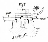
I have some slightly off topic questions. Say we have brass bolts securing cell buss bars. Electrons can flow either through bottom of the buss bar (that makes contact with the cell) or the top of the buss bar (that makes contact with the top of the bolt. What percent of electrons flow through the top of the buss bar? Now the main question. The BMS requires a voltage sense connection at the cells. A ring terminal is inserted between the top of the buss bar and the bolt head. The bolt head no longer makes direct contact with the buss bar. Is battery resistance increased substantially?
I believe in the automotive industry you can have a maximum stack of 5 ring terminals. I was told that each terminal adds 0.5 to 1 m ohm of resistance for 0 awg connections.
ultrakiev
New Member
- Joined
- Feb 25, 2021
- Messages
- 95
I think you right. I had once situation like this. I installed A/C on a dump truck and it fried harness of the recently installed A/C unit, because old OEM starter had poor ground connection. So when I installed new unit with new good ground at the battery... on truck start up, starter found new path to ground , 700A thru 10GA ground wire and caused entire harness to melt. I like your theory!I used to do car audio competition, and this was always a highly debated subject.
1. When you say through the BODY, you want the conductor to be the unibody or the frame, not the body pieces of a body on frane vehicle.
2. A fundamental people get wrong is that the ground point of your circuit is NOT the battery negative terminal. Its the frame/unibody of the vehicle. Repeat as often as needed because...
3. Youve got a safety issue if you hook up any accessory to a vehicle and use an additional cable to run ground back to the starting battery. If the OEM neg cable fails when you crank the starter, its full current goes through that accessory. Fire, smoke, ruined component.
Really, just never forget #2. The common ground of our circuit is not battery negative, its vehicle chassis. With that in mind the conclusion is its pointless to run additional negative cables from components to power supplies. #3 tells us: Redundancy is not insurance, its liability.
I was aware of that. However, the example chosen was somewhat unfortunate in my opinion - hence. That the chassis is the best conductor is not in dispute, it seems to me that there should be a consensus on that. The question is whether you should use the chassis at will. If HaldorEE says he only uses one point then I can understand that. In my situation, I prefer to use as few earth points as possible. For the full reasoning, see the answer above (with the formula).My comment regarding using stainless steel bolts to secure copper buss bars for battery cells was in response to the poster who was trying to make the point that using vehicle chassis as a electrical conductor is a very bad idea. I'm at the other end of the spectrum. Chassis with all its mass is an excellent conductor.
What you have written I have drawn. In my opinion, the current will flow through the path of least resistance. Brass, depending on the alloy, has about a 4 times higher resistance than copper and 3 times more than aluminium. The current will therefore mainly flow through the thick arrows and to a considerably lesser extent through the thin arrows.I have some slightly off topic questions. Say we have brass bolts securing cell buss bars. Electrons can flow either through bottom of the buss bar (that makes contact with the cell) or the top of the buss bar (that makes contact with the top of the bolt. What percent of electrons flow through the top of the buss bar? Now the main question. The BMS requires a voltage sense connection at the cells. A ring terminal is inserted between the top of the buss bar and the bolt head. The bolt head no longer makes direct contact with the buss bar. Is battery resistance increased substantially?
I believe in the automotive industry you can have a maximum stack of 5 ring terminals. I was told that each terminal adds 0.5 to 1 m ohm of resistance for 0 awg connections.
The prerequisite is that the A-surfaces have been prepared properly and that a sensible tightening torque has been used. In that case, current only flows through asperities that make metallic contact. If you consider that that is only a fraction of 1 percent of that surface, it is reasonable to take a very limited resistance into account.
Rough math with the values you mention....
0 AWG is ~50 mm2, 5 A per mm2 means 250 A.
1 mOhm... Voltage drop is 250 * 0.001 = 0.25 V
Power loss... 0.25 V * 250 A = 60 Watt
That raises red flags (fire hazard) and should be an indication to re-evaluate such a connection: Are the used values realistic? If yes, spread those 250 Amps over more points for example (edited after making a stupid mistake).
Food for thoughts ;-)
Attachments
Last edited:
1/0 cable is rated for 170A max at 90C insulation. Your calculation is a bit out of bounds. The point I was trying to make is that contact resistance is appreciable. While copper may have 4.4x lower resistance than brass, those resistance are likely much smaller than the in series contact resistance. The ring terminal doubles the contact resistance to the upper section of the buss bar. My gut feel is that there's a significant increase in battery resistance when a ring terminal is inserted between the bolt head and buss bar.
Probably. However, a power loss of a fraction of that value would still make me worry.1/0 cable is rated for 170A max at 90C insulation. Your calculation is a bit out of bounds.
The point I was trying to make is that contact resistance is appreciable. While copper may have 4.4x lower resistance than brass, those resistance are likely much smaller than the in series contact resistance. The ring terminal doubles the contact resistance to the upper section of the buss bar. My gut feel is that there's a significant increase in battery resistance when a ring terminal is inserted between the bolt head and buss bar.
I can go along with that reasoning. That makes the previous sketch less valuable.
The way I understand it is that you can influence the resistance of a contact surface considerably by removing oxides and dirt and by applying a large force to the surfaces. After that you will always remain with a relatively small A surface through which the current has to pass and you will always have a minimal resistance as a result.
So, for example, you could say that it is not a bad idea to solder a wire in the middle of the bus bar to avoid using ring terminals.
You will probably want a brass washer at the bolt head - annealed copper is soft. This will increase the resistance even more.
Contacts in combination with large currents prove to be tricky. The adapted sketch with A-planes bold...
I would prefer to use a threaded rod, as deep as possible in the battery pole.

Similar threads
- Replies
- 10
- Views
- 586
- Locked
- Replies
- 1
- Views
- 2K