Hi all. Probably a very silly question but I need help please. I have a Victron Multiplus-II 48/15000/200-100 230v Inverter. I am in France and the solar system is around 60 metres from the main house. The previous electrician cut the house cable feed and inserted two 16mm2 cables in a ring from the house now 120 metres long, into the solar shed and back to the house in a ring main. This meant that my house was now suffering huge voltage drops. The solar room wiring was intended to only run the inverter and is not back fed to the mains for income. This also meant that in any working situation on the solar area the power was cut to the house. It was my belief that the inverter would run perfectly OK with its own fused circuit from the solar room into the house mains keeping the house circuit as it was. This spur cable would be a dedicated cable. The actual house mains from the power grid is 32mm2. Other electricians here are very cautious and want to install a 50mm2 ring main which seems to me excessive. For clarity I have 40 410w panels feeding the batteries through MPPT's. Everything is new Victron and as yet I have not connected it up because I had so many problems with my old inverters. I now believe that this was likely because of power loss. Can anyone advise me please? My existing house electric consumption is conventional lighting, heating and general house connections. Only two people use the house.


You are using an out of date browser. It may not display this or other websites correctly.
You should upgrade or use an alternative browser.
You should upgrade or use an alternative browser.
Wiring an Inverter into the mains
- Thread starter Normandie
- Start date
Hi Normandie,
You can calculate the voltage drop using an on-line voltage drop calculator. For example...
 www.cse-distributors.co.uk
I hope this helps.
You can calculate the voltage drop using an on-line voltage drop calculator. For example...
Voltage Drop Calculations
Voltage Drop Calculations. The voltage drop of any insulated cable is dependent upon the route length under consideration (in meters), the required current rating (in amperes) and the relevant total impedance per unit length of the cable.
I hope this helps.
Thank you Bongbong. At this stage I need to know if I can wire the inverter on a spur cable complete with its own circuit board and breakers. Once this is confirmed or declined then the voltage drop can be determined. Thank you so much for your kind response.
Neil H
New Member
Yes you are right power for the house should not go all the way to the shed and back
Neil H
New Member
if you mean the cable feeding the shed from the house 100% yes as this is then protecting the cable/equipment
Thank you Neil. I was totally confident from my own perspective until I was persuaded otherwise. So in practice as long as I install the spur circuit from the mains feed in the house and also install in the solar house a complete circuit board with grounded earth, lightening protection circuit breaker, and 63 amp digital breaker will it all be good to go. The two input and output wires from the inverter will then connect to this circuit board? Sorry to be a pain.
MisterB1959
Solar Enthusiast
- Joined
- Oct 22, 2022
- Messages
- 355
i think you really do need a competent electrician to advise as there may be reasons why it has been set up like this, i assume the ring main to the shed also supplies power to the shed and not just for the inverter? but i am only assuming as we dont know the set up or why the electrician chose that option.
In my opinion, if its only supplying the inverter, then it only needs to be one cable direct to the inverter if its a bi directional inverter.
The size of the cable should be calculated using a calculator (example above)
In my opinion, if its only supplying the inverter, then it only needs to be one cable direct to the inverter if its a bi directional inverter.
The size of the cable should be calculated using a calculator (example above)
Can you post a schematic diagram of your existing and intended wiring.
From what I am reading you have 16kWp of panels which is a sizeable system. You also have two 16mm2 cables between house and inverter location. What we don't know is what is your typical daily energy consumption and what is your maximum load. You say you have siginificant voltage drop - what is significant - can we have some numbers to work with.
I'm not a sparky, but I would not expect 'significant' drop with 16mm2 cable over that distance with regular household usage. Maybe you have a heat pump or EV or swimming pool heater?
The reason for the loop from house to inverter would, in my mind, have been installed, so you can operate in an off-grid mode, rather than grid tied. Grid-tied, as @MisterB1959 mentioned would only require one cable.
Thank you MrB1959. The cable supplying the shed is only for the solar. It has no other circuits involved. The Inverter is a Victron Multiplus-II 48/15000/200-100 230v Inverter. I understand this can be set either way. Kind regards.i think you really do need a competent electrician to advise as there may be reasons why it has been set up like this, i assume the ring main to the shed also supplies power to the shed and not just for the inverter? but i am only assuming as we dont know the set up or why the electrician chose that option.
In my opinion, if its only supplying the inverter, then it only needs to be one cable direct to the inverter if its a bi directional inverter.
The size of the cable should be calculated using a calculator (example above)
I will attempt a schematic diagram but it will be basic SeaGal. I will provide some more detail. Yes the kWp is correct. This was built for allowing extra batteries for storage capacity. We have six Pylontech US3000 batteries at present but intended to increase. It seemed easier to build in expansion this way. The alterations put in to the house making it a ring main were never intended. The consumption drop was because we ended up having the whole property running on an 16mm2 cable with a run of 120 metres. Our worst ever consumption was 2915 kWh in one month. This was in 2022. since then we streamlined our use of power and in Oct 23 to present day has been 990 kWh, 1822 - 2357 - 2624 - 1612. We have a heat pump, ordinary white goods, no tumble dryer etc. Whilst the house was still connected to the 120 metre ring main we would have LED lights drop to almost off. Cooker, kettle etc would go very low. We never measured the drop. The house is no longer on this ring and everything is working OK. No swimming pool or other heavy usages. The reason for the loop was because the electrician insisted that because there were two nodes on the previous inverter (as most inverters) labelled in and out, then the inverter could not work or switch between mains supply to the inverter and inverter supply to the mains. I am not an electrician and cannot begin to comprehend, however he insisted that a loop or ring main was a critical requirement. I had a full system installed in the UK a few years ago. They connected the inverter into a spur connection and it worked fine. This system was 12 kWh and we never had a single issue. I will try and draw a diagram. Thank you all for this assistance.Can you post a schematic diagram of your existing and intended wiring.
From what I am reading you have 16kWp of panels which is a sizeable system. You also have two 16mm2 cables between house and inverter location. What we don't know is what is your typical daily energy consumption and what is your maximum load. You say you have siginificant voltage drop - what is significant - can we have some numbers to work with.
I'm not a sparky, but I would not expect 'significant' drop with 16mm2 cable over that distance with regular household usage. Maybe you have a heat pump or EV or swimming pool heater?
The reason for the loop from house to inverter would, in my mind, have been installed, so you can operate in an off-grid mode, rather than grid tied. Grid-tied, as @MisterB1959 mentioned would only require one cable.
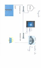
Hello all. Please don't get upset at my lack of ability here. I hope it is enough to give you a basic idea. On the ring-loop main the EDF supply goes from the meter - then is joined by a connector to the 16mm2 cable, this goes to two consumer units. The first one connectors to the OUT on the inverter. The second consumer unit connects to the IN on the inverter and then goes back to the House consumer unit via the second half of the 16mm2 cable. This completes the circuit.
On the proposed circuit everything from the mains etc to the house and all house circuits are original. The idea is for one of the 16mm2 cables to run from the house connection via an interrupter switch, then terminate at a consumer unit. The inverter would be wired into this unit, providing IN and OUT connection to the Victron.
Kind regards
Attachments
Thanks, the extra detail is helpful. These are my thoughts, but bear in mind I'm not a sparky...
a) When you mention the "Ring-mains" connection, I am assuming, being British, that you are referring to how we wire our house power circuits in the UK - that is a ring fully connected, so that a load at the far end of the ring will share current on either half of the loop. So, in your case, your "ring" of 16mm2 is equivalent to a single cable of 32mm2 of 60m length. Hence I didn't see why you refer to 120m of 16mm2... that would only be the case if you had a radial circuit, albeit physically configured as a loop, rather than a "ring".
b) Either way, I would not expect to have such voltage drop issues with the loads you mention. It is possible (though no longer provable) that there was a high resistance connection somewhere causing such a loss.
c) With your proposed diagram; that, in essence looks OK and "standard". However, if you already have a "ring" or "loop" of 16mm2 cable, already laid in the ground it would make sense to parallel those cables to give you 32mm2 over 60m. Not that you need that size of cable to carry the current, but doing so will minimise voltage drop/rise and also minimise power losses. If you want to configure a backup circuit in the future you could re-configure, but IMHO if you've already got the copper in the ground then might as well use it.
d) Connecting your inverter feed/supply to the house CU is common, certainly in the UK. I don't know what French regulations would apply, but in the UK, BS7671 regulation 551.7.2 dictates "... Regulation 551.7. 2 relates to where a generating set is connected via an LV assembly e.g. a consumer or distribution board. The rated current of the LV assembly must take into account the additional supply from any generating set(s) ". This means that the CU will need to be rated to the sum of the PV and the incoming EDF cut-out fuse. Hence, your 12kW inverter will be able to produce 53A at nominal 230V. So, if your incoming fuse from EDF is (for example) 80A, then your house CU must be rated greater than 53A+80A = 133A.
e) Obviously you will need to have suitably sized MCB in both CU's to protect the wiring. It sounds as though the smallest wire will be that from the garage CU to the inverter, rather than between CUs.
Thank your so very much for your reply. In answer to a) Yes you are correct. I am not an electrician as you have gathered, but I refer to the loop of the two 16mm2 cables joined as a loop.
b) I am sure that the loss may have been caused partly by the old MPP inverters. This could have at least been contributory.
c) Yes I agree regarding the 'spare' cable in principle but I was hoping however to add a second inverter using this cable. I have a set of SOK five 5000 batteries that just might give me another target toward coping longer without using the grid.
d) The French system is changing regularly and I do not understand it. I do use French regulated electricians however to check what is allowed. I will certainly follow your recommendations. At present the house is 70A. I will ensure the correct calculation is done as you have explained, thank you.
e) I believe that 63A MCB's is appropriate. If I am wrong we will change it. The supplier recommended 40A but I will again check what is suitable.
Thank you once again for all of your comments. This forum is so very good because of the people in it.
Kind regards
Normandie.
Similar threads
- Replies
- 21
- Views
- 604
- Replies
- 6
- Views
- 193