diy solar

diy solar

Islanding. grid protection, and whole house UPS

xcentric

Learning, fast and slow.....
Joined
Sep 17, 2023
Messages
147
Location
UK
I'm a bit confused about islanding and whole-house backup. I get that hybrid systems need to know when the grid is down and not divert energy into the grid in that case. But consider the diagram below:
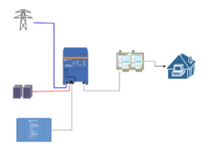
Screenshot 2024-03-05 at 23.06.48.png


Inverter, batteries and solar, attached to grid and consumer unit into house.

If the dark blue line goes down, then no power should flow from the inverter to the grid. I get that. But as many inverters can detect this, why can they simply not send power down that line, and continue to run the main consumer unit from the solar and batteries as much as possible (I know if the house is pulling more than the inverter can provide it'll fail, but ignore that).

If I added a manual transfer switch into that blue line, would it mean that if I switched that when there was a power cut so that the inverter was actually isolated fro the mains, it could then run independently? Or if it was an automatic transfer switch, that would happen automatically?

I know that a common solution is to have some critical loads running off a separate inverter outlet, but for my kids, tv, xbox, internet and wifi are all critical and so major rewiring at the consumer unit would be needed.....

This seems to be an obvious and useful scenario but not clearly supported, so what am I not getting?
 
nb I know this isn't the usual way they are connected - inverter feeding into consumer unit in parallel with grid - but my point is why not design them this way. As @BentleyJ says above, because the inverter disconnects when grid loss detected, if wired like this then house would continue to function.

Is it just that building them with passthrough and the sensing for the grid internally is complex to do?
 
Which hybrid inverters with batteries do not act like a whole house UPS when the grid fails?

Or maybe I’m not understanding what that consumer unit is above
 
I am not an electrician, but as a homeowner I could wire the inverter to the consumer unit, wire in a sub-panel, and move breakers to it.
I could not wire the inverter between the grid and consumer unit.

I think that is why people do it the first way.
 
If I added a manual transfer switch into that blue line, would it mean that if I switched that when there was a power cut so that the inverter was actually isolated fro the mains, it could then run independently? Or if it was an automatic transfer switch, that would happen automatically?

There are two ways it's done in the US with new hardware

Microgrid Interconnect Device
- ATS + sensors to detect when the grid goes down. If grid goes down the ATS opens that connection, and then power can be pushed towards the MID

Hybrid inverter with bypass sized to carry 200A. And then use hybrid inverter ahead of all house loads. The hybrid has all the necessary sensors.

XW Pro has some way to use an external relay but I don't know what kind of sensors it adds upstream of the external relay.

In all of these scenarios if the main panel is non-convertible (un-removable N-G bond) then a lot of moving of circuits will be needed.

Flipping manual transfer switch is not good enough for code because the inverter does not know that you did it correctly.
 
The recommended threads address this pretty well ("Similar Threads" section as I see right now).

TIL about the magic disconnect relay that Tesla can install as a meter base adapter. Sounds fancy and expensive.

 
When the inverter is passing through 200 amps, it is easier for there to be, in essence, a wire from the grid input to the load output, and the inverter sits on the side taking and pushing power to the line.

When the grid goes down, the inverter flips an isolation relay, and disconnects the grid (some inverters do not have this).

The alternative is for the inverter to sit between the grid and load. Then you need all the circuits to take the power from the grid, and push it to the load. Big stuff for 200 amps. Not so hard for 20-30 amp limited inverters.
 
Which hybrid inverters with batteries do not act like a whole house UPS when the grid fails?

Or maybe I’m not understanding what that consumer unit is above
most of them They only provide output on the 'essential loads' output.
 
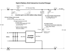
When AC input if first supplied, the pass-through relay is (must be) open. Inverter first slowly syncs to AC input phase and voltage before closing pass-through relay. This takes a couple of seconds, after which you can hear the pass-through relay engage.

Usual mode is inverter runs in sync and in parallel to grid (after sync'g to grid).

When grid collapses inverter is hit with a momentary surge current overload that causes pass-through relay to release connection to AC input. This all happens in less than 4 milliseconds (about one quarter of an AC cycle).

AC1, grid port pass-through relay on Quattro has 100 amps AC maximum capability.

There is actually two pass-through relays in Quattro, one for AC1(grid) and one for AC2(generator). Only one can be used at a time with grid port taking priority if both AC inputs are present. I believe the Gen port pass-through relay is rated for 50 amps max.

You can run in standby on inverter until grid drops but that takes a bit longer to pick up loads and more likely to have enough of a time gap glitch to cause some appliances to reset. In standby mode, inverter is inactive, but controller has sync phasing of grid before it dropped so it knows how to startup inverter in AC phase sync to what grid would have been if still alive.

For anti-islanding, it is actually tougher for inverter to detect an open AC input. Inverter is slaved to AC input when pass-through relay is engaged and usually gets phase corrections from AC input master that keeps inverter in sync.

Either getting too many zero crossing without phase corrections or inverter wandering high in frequency causes inverter to open pass-through relay after you open AC input breaker. This may take a few seconds to happen, during which time there is inverter AC voltage present on inverter AC input terminals.
Sjimplified Hybrid inverter diagram.png
 
most of them They only provide output on the 'essential loads' output.
Dunno about most of them, but the EG4 118KPv has a 200A transfer switch built in, as do the Sol-Ark residential series. No need to have the 'these are the appliances I don't want to work when the grid goes down' solution.
 
Dunno about most of them, but the EG4 118KPv has a 200A transfer switch built in, as do the Sol-Ark residential series. No need to have the 'these are the appliances I don't want to work when the grid goes down' solution.
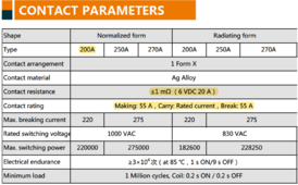
Look at specs on pass-thru relay. 200A continuous, 55A make and break.

It is grid glitches causing break open and re-makes under large current that is hard on the pass-through relay contacts.

CHAR-C Series 200A
 

Attachments

  • CHAR-200-250-270-Series.pdf
    190.3 KB · Views: 8
Look at specs on pass-thru relay. 200A continuous, 55A make and break.

It is grid glitches causing break open and re-makes under large current that is hard on the pass-through relay contacts.

CHAR-C Series 200A
I haven't gotten mine yet, that's the relay used in the 18Kpv? The spec is very confusing:
Screenshot 2024-03-06 at 1.25.03 PM.png

So that's 13KW, which most of the time my load is under that. Not sure if two inverters in parallel helps or not, I can't imagine the relays actuate at exactly the same time...
 
I haven't gotten mine yet, that's the relay used in the 18Kpv? The spec is very confusing:
View attachment 200416

So that's 13KW, which most of the time my load is under that. Not sure if two inverters in parallel helps or not, I can't imagine the relays actuate at exactly the same time...

The make/brake is a harsh disconnect. Think of it as flipping a switch under load and getting a brief arc. Fortunately it’s an AC arc

I think the second one to flip will always take the full hit? Maybe. First one will have minimal arcing bc the second closed path will preferentially take the current anyway

It’s possible if the relays open/close at random times relative to each other the wear will be spread evenly. I don’t know if this is an accurate model. Possibly one is biased towards being faster than the other
Yeah, kind of a mess. I still don't understand how:

Contactrating: Making:55A,Carry:Ratedcurrent,Break:55A
and
Max.breakingcurrent 220 275

go together. Since I'm planning on being disconnected from the grid anyway, it's more a thought experiment for me, but I'd like to understand the ramifications if I recommend the systems to neighbors.

If you are set for Zero Export, is there an easy way to keep the grid power under a certain number?
 
Ah, I didn't see that conflict between the two different breaking ratings. No clue.

Zero Export -- you have to check what's available on your equipment. And evaluate the risk of being detected if you don't have an interconnect agreement.
 
In U.S. and European engineering specs it is a 55A relay. In Chinese engineering specs it is a 200A relay if you don't allow greater than 55A as it closes and don't open it again until current is below 55 amps.

Making and breaking 200 amps would require a much larger relay with massive contacts.

Reference the size of a 200 amp main breaker in main AC breaker box and it is not designed to take too many pops. Its two contacts (L1 & L2) are about the size of your thumb and about half as thick as your thumb.

Another similar size reference is a UL approved 200A whole house generator transfer switch.

The relay specs contact series resistance of <1 milliohm. 1 milliohm x 200A^2 is 40 watts of contact heating which will get very hot with little heat dissipation. There are two versions of relay listed in specs. 'Normal' form and 'Radiating' form. It appears the 'Radiating' form has nothing more than standoff legs to allow some air flow under relay before the terminals get to PCB board to allow some cooling heat transfer of terminals, so it does not melt the solder connections on PCB.

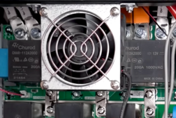
SolArk 15K has an extra fan specifically for the pass-through relays mounted directly over them.

Solark 15K pass-thru relays.png
 
Last edited:
In U.S. and European engineering specs it is a 55A relay. In Chinese engineering specs it is a 200A relay if you don't apply greater than 55A before it is closed and don't open it again until current is below 55 amps.

Making and breaking 200 amps would require a much larger relay with massive contacts.
Do you know what size relay Enphase and Tesla Microgrid Interconnection Devices use?

Along the same lines, I think EG4 and SolArk also showed some MID looking boxes at a recent convention.
 
The make/brake is a harsh disconnect. Think of it as flipping a switch under load and getting a brief arc. Fortunately it’s an AC arc

I think the second one to flip will always take the full hit? Maybe. First one will have minimal arcing bc the second closed path will preferentially take the current anyway

It’s possible if the relays open/close at random times relative to each other the wear will be spread evenly. I don’t know if this is an accurate model. Possibly one is biased towards being faster than the other
In smaller inverters such as Magnum MS4448PAE, or Schneider XW, when a relay board goes in a stacked system, it is often a single inverter's relay. Under specific scenarios you will get multiple units with burnt relays, but I would say 95% of the time there is only 1 that's burnt or there is 1 that is by far the worst! What often happens is that once a relay starts having a "textured surface" (for lack of a better description) from the arcing, it gets worse from there because I think the arc is jumping the worst off of whichever tiny portion is closest as the contact opens. Then that tiny point "catching" the arc gets way hotter and melts more. That pulls it further off the contact, making it just snowball from there.

Most times relay failure comes from arcing during disconnect, and NOT during connection to grid/gen! This is mostly due to the inverter being synched up to the AC source during connection, as well as charger being "off" until after connection has been established. If I'm not mistaken, some inverters (such as Sch XW, I think...?) will actually even try to pull the contacts at the zero A point in the cycle, therefore mitigating the arc during connection.

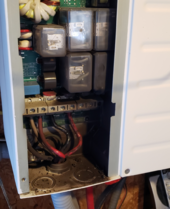
Here is one of the worst relay meltdowns that I have seen!

1709819400815.png

There is literally melted solder off the PCB laying at the bottom in little balls!

Something to keep in mind (This goes for single inverter installs as well.) is that if you have a scenario where you will often be charging heavily from an AC input (This is by far the worst, and most common, in off-grid installs, where you only run the gen for charging.), oftentimes the charging current going through those contacts is the heaviest load to the relay. If voltage drop happens too quickly, I think the relay is often opening before the inverter has time to change from charging to inverting. (I believe that is controlled by adjusting phase angle relative to AC source, as well as possibly voltage level relative to AC source. Someone else on here may know the technical details better on this...) I have seen an XW relay (60A rated) welded to the point of killing the FET board as well, and the passthrough loads were only ~2,000 watts (~8.5A pr leg). The killer was an AC compressor with no soft start, running directly on the gen (~40kW running all day during store open hours) causing massive voltage drop on the AC lines multiple times pr day, therefore causing the inverter to disconnect under heavy charging loads. We got a soft start installed and never had a relay issue on that job since then! Generally, if the inverter's max charge rate is lower, there is a LOT less chance of the relay getting toasted!
 
Back 25 years ago, Trace used a Deltrol 375 three pole, 30A/pole 3PDT relay with the three poles connected in parallel for their 60A pass-through AC current spec on inverter.

They had a debate with UL over using 3x 3 pole 30A relay contacts to achieve a 60A capability. They won the debate with UL by arguing the three poles were mounted to same mechanical rocker bar within the single relay and would have simultaneous opening and closure.

A poor engineering practice used in Chinese inverters is putting small, separate, 30A or 40A 'hot water heater class' relays in parallel to achieve their higher pass-through current spec for inverter. Separate relays will not have precisely the same opening and closure timing.
 
Back
Top