diy solar

diy solar

Wiring & Design Help Needed

cheeese

New Member
Joined
Sep 30, 2019
Messages
4
I've been chugging along buying and designing our solar and electrical set up for a bus we recently purchased. Watching and learning from Will's YouTube series has been a massive inspiration (cheers buddy).

Up until yesterday, time wasn't that important. However, we received a Notice to Vacate from our landlord yesterday, who wishes to move back into her property (oh, the joys of renting). SO, the bus needs to be ready in 60 days ?.

Here are the (very) basic specs of the set up:

- 1000W solar panels
- 9.6 kWh LifePo4 battery bank
- 4000w Inverter
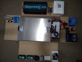
IMG_20190930_200414.jpg

The set up goes into a boxed area on the bus and as you can see in the picture, the walls are all laid out flat here.

Where I need help:

- With very limited space to work in, placing all parts in their most effective position
- Wiring between all parts, in particular the correct gauge wires for efficient power supply
- Correct safety breakers set up to protect us and the equipment

I'd actually be happy to pay someone for the job too if they are interested. If anyone is interested, I can shoot them a detailed parts list and dimensions of the space we're working in.
 
Not bad, 24v, 230Ah bank...
1000watts isn’t much, but you likely don’t have many constant loads. Still, more is better.
Are you tying the bus alternator in to boost charge when driving? It looks like a decent set of parts so far.
 
Got a picture of the bus so we can see what kind of space we are talking about? Does it have a basement like an RV? Is it a schoolie? If so you can make a box and remove 2 seats to have a place for it. The vehicle is something we'd need to see to visualize for suggestions.
 
Thanks for the replies and sorry about my slow response.

Not bad, 24v, 230Ah bank...

24v 400Ah LifePo4 bank from Aliexpress. Super pumped about it.

1000watts isn’t much, but you likely don’t have many constant loads. Still, more is better.

I know, and I'm thinking about adding outlets on the side of the bus to plug in more panels when we stop at a location for a longer period. I've maxed out all space on the roof.

Are you tying the bus alternator in to boost charge when driving? It looks like a decent set of parts so far.

Yes, initially I was keen to do this (and kind of still am), but yesterday I measured the amps from the alternator to the battery and it's only feeding in 7amps when idle. Was a little disappointed with this number.

Got a picture of the bus so we can see what kind of space we are talking about? Does it have a basement like an RV? Is it a schoolie? If so you can make a box and remove 2 seats to have a place for it. The vehicle is something we'd need to see to visualize for suggestions

Good point, it's a 1984 Mazda T3500, used to look like this:

i686102.jpg

There's the possibility to build a compartment next to the start battery (underneath the bus), but for version 1, we're putting the battery and electricals above the starter battery, in a compartment under a seat we made that is 700mm long x 290mm wide x 370mm high. This will house the battery bank and all electrical components.

YI... don’t expect that inverter to provide for 4KW loads...
This. Max would be 2500-3000 continuous for a long service life. It radiates 'big claims'.

Yeh, I know, I've seen the videos and read the reviews. But it's the only one that fits for now (until we build a better compartment under the bus). Then I'll defo upgrade to the Victron.

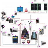
Here is my first version of the wiring diagram:

wiring_diagram_v1.jpg
And parts list:
1250W 12V Monocrystalline Solar Panels
2400AH 24V LifePo4 Battery
3Victron SmartSolar 100/50 MPPT Solar Charge Controller
4Victron Smart Battery Sense - Voltage and Temperature Sense
5Victron Smart Battery Monitor BMV 712
6Victron SMART Battery Protect 12/24V-220A
7Car Boat Battery Isolator Switch 24V Power Cut On/Off Master Disconnect
860A Circuit Breaker Switch
9200A Circuit Breaker Switch
1012V Push Button Switch Start Momentary ON OFF
11Black CMS 15Amp Plug Power Inlet
12Buss bar power distribution block Terminal Block H/Duty 300amp Sealed
13DC/DC Converter Regulator 12V Step Up to 24V 15A 360W
14CMS 1000MM Circuit Breaker Connecting Lead
154 Way Pole Switchboard Surface Mount Distribution Board Din Rail Mounted
16Safety Switch Circuit Breaker Combination RCD MCB 2 Module Double Pole 16 Amp 4.
17Safety Switch Caravan RV True Double Pole 16 Amp 4.5kA Single Module RCD/MCB GEN
18Voltage Sensitive Relay, VSR module 12V 125Amp
19Automatic ATS Dual Power Transfer Switch
2024V 45A Battery Charger
214000W Pure Sine Wave Power Inverter 24V 220V
22AC 240V to DC 12V 360W 30A Car Power LED Converter Transformer
23Class T Fuse
24Pro Installer Class-T Fuse Holder
25ST Blade Fuse Block - 6 Circuits with Negative Bus and Cover
26Power Point Double Pole 10 Amp GPO Outlet Caravan RV Trailer Construction
27Waterproof DC/DC Converter Regulator 24V Step Down To 12V 30A 360W
28100A Circuit Breaker Switch

I am Australian :), so you're looking at a metric system + 240v.

Please let me know your feedback, concerns, improvements on the above. Really appreciate the help and enthusiasm :).

The next step is to work out wire sizing and arrange it all to fit into the space we have.

Disclaimer: I am not an electrician, the above diagram is not to be taken as correct or safe and I understand any advice given here is only advice. All work will be undertaken by a licenced electrician.
 
#7, that switch really isn't up to the job. I'll take a stab that you have spec'd it to handle the current but not the voltage. If you open the switch with the panels getting a reasonable amount of light the panels will leap up to VoC. From the 18.6v I'd guess the VoC of each panel might be 24v so the switch needs to be able to break 48v as a minimum. If it can't a persistent arc might form and start burning away at things.

IMO a proper DC breaker would be a better choice. It'll have an arc trap too so if anything does go wrong it should be able to extinguish the arc before things get nasty.
 
Google Voltage Drop Calculator to help with determining wire sizes.

Good call, found some calculators, using them now.

#7, that switch really isn't up to the job. I'll take a stab that you have spec'd it to handle the current but not the voltage.

Here are the specs:

Code:
Battery Disconnect Switch - Switch - They are offered as main disconnect switches. For use with systems under 60 volts.
Capacity - 1250 Amps momentary, 275 Amps continuous @ 12V DC.
 
Specification:
Selector Position: ON - OFF
Voltage: 0V - 60V DC
Rating: 275 Amps Continuous, 1250 Amps Intermittent
Base: 2.85" x 2.85" (72.5mm x 72.5mm)
Height: 2.90" (73.5mm)
Terminal studs: 10mm diameter

Nabbed the idea from AM Solar: https://static1.squarespace.com/sta...5e4966baef193a5fa/1539199585230/99-SKOSIG.pdf
 
OK, if it can handle 60VDC it should be able to safely disconnect the panels.
 

diy solar

diy solar
Back
Top