diy solar

diy solar

Chinese inverter discharges batteries without anything connected

Light bulb moment.

There is a way that this could be solved if the AIO manufacturers incorporated it. At battery low voltage set point instead of going into shutdown the unit could check for AC power and engage DC charging at a low amperage enough to maintain AIO operation and above battery low voltage cutoff. Note: this is different than using set amperage charging while in AC pass through. (many do not want to charge from AC so operate in PV only charge mode). It would pass off AIO's power needs to the AC side until PV charging had raised battery voltage sufficient enough to go out of AC Bypass.
 
Good light bulb, but I'm not aware that Voltronic Axpert is possible to do this.
But I have a very similar plan to overcome this!
Using "Charge Source Priority Timer" to change from " Solar only" to "Solar & Utility" for 1-2 hours (don't know if Axpert Timer allows 1h ... discussed in another thread) and by this allow the battery to get charged with current from grid to compensate for the "idle current".
If set properly, this extra computational charge will hopefully keep my Battery from triggering low voltage shut down.
 
The inverter should shut down when it reaches low battery cutoff. It will still draw some power to run microcontroller and display but it should be a small amount of power.

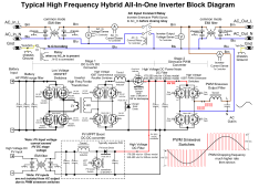
When AC input is present, cheap AIO HF inverters can do slightly different things depending on particular model and user settings. Cheap HF inverters have trouble switching between charging battery and supplying AC output from inverter. They need about 30-100 msecs to make the switchover which results in inverter dropping out for that time period.

On cheap HF inverters, when AC input is present, the AC input is just passed through to AC output and inverter circuitry is locked into battery charging mode tapping power from AC input. If solar is present, and depending on user setup priority, the PV power goes to supplementing AC output and/or battery charging.

Some really cheap AIO inverters have to dedicate the AC output PWM sinewave generation circuitry to either charging battery or supplementing AC output from solar power when AC input is present. You can have PV supply one or the other but not battery charging and AC output supplementing at the same time. This is because it uses the AC output PWM H-bridge to regulate charging preventing its use for sinewave output generation to supplement AC output from PV power. Units that allow simultaneous charging and AC output supplementing have an extra buck switcher IGBT or MOSFET switcher and diode in the battery to HV DC converter path. This is the more common configuration.

Just about all hybrid inverters these days have a small AC input power supply that will power the microcontroller and display from AC input if present, otherwise power is supplied from battery or PV power. Since PV controller takes some overhead power, it comes from battery source so if low battery is tripped it may also shut down PV controller. This is a 'catch22' as battery is low on charge, PV power is available to provide charging, but because of low battery it does not allow PV controller to operate.

Some models will run PV charge controller from PV power if there is enough PV power available. This is a little trickier for PV charge controller as it may get stuck in a startup-shutdown recycling when available PV power is marginal.

HF inverter block diagram.png
 
Last edited:
Light bulb moment.

There is a way that this could be solved if the AIO manufacturers incorporated it. At battery low voltage set point instead of going into shutdown the unit could check for AC power and engage DC charging at a low amperage enough to maintain AIO operation and above battery low voltage cutoff. Note: this is different than using set amperage charging while in AC pass through. (many do not want to charge from AC so operate in PV only charge mode). It would pass off AIO's power needs to the AC side until PV charging had raised battery voltage sufficient enough to go out of AC Bypass.
This is how my MPP solar units work
 
...

When AC input is present, cheap AIO HF inverters can do slightly different things depending on particular model and user settings. Cheap HF inverters have trouble switching between charging battery and supplying AC output from inverter. They need about 30-100 msecs to make the switchover which results in inverter dropping out for that time period.

On cheap HF inverters, when AC input is present, the AC input is just passed through to AC output and inverter circuitry is locked into battery charging mode tapping power from AC input. If solar is present, and depending on user setup priority, the PV power goes to supplementing AC output and/or battery charging.


...
Typically the user sets charging mode to be from PV only. So at battery transfer to utility setpoint the unit goes into AC pass through but no charging occurs. This is the point that the batteries will eventually get drained because either they are insufficient to carry idle load through night or a person experiences bad weather for PV charging.

That is where my solution comes into play. The unit can charge when in AC bypass but the user has it set for no charge. Battery low voltage set point is reached. The unit engages a minimal charge current. It does not require a massive rethinking of AIO design. It is simply a programing change.
 
Cheap HF inverters have trouble switching between charging battery and supplying AC output from inverter. They need about 30-100 msecs to make the switchover which results in inverter dropping out for that time period.
The unit can charge when in AC bypass but the user has it set for no charge. Battery low voltage set point is reached. The unit engages a minimal charge current. It does not require a massive rethinking of AIO design. It is simply a programing change.
Exactly how my MPPSolar PIP3048LV-MK units work.
50v low is reached, bypass is engaged for the loads as well as about 1.75 amps of what I refer to as bleed charge. Solar first, utility charge disabled. You need this little bit of extra because when charging the battery, the battery is no longer available as your buffer for movement in your loads. I like this because when I reach low voltage it pulls the batteries back up off of the bottom.
 
Seeing your model in your Signature I looked up the operations manual. It does not mention that it can maintain battery when charging is set to PV only. I would think that would be a important piece of information.

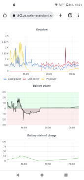
Thanks for the graph!
 
The inverter should shut down when it reaches low battery cutoff. It will still draw some power to run microcontroller and display but it should be a small amount of power.

When AC input is present, cheap AIO HF inverters can do slightly different things depending on particular model and user settings. Cheap HF inverters have trouble switching between charging battery and supplying AC output from inverter. They need about 30-100 msecs to make the switchover which results in inverter dropping out for that time period.

On cheap HF inverters, when AC input is present, the AC input is just passed through to AC output and inverter circuitry is locked into battery charging mode tapping power from AC input. If solar is present, and depending on user setup priority, the PV power goes to supplementing AC output and/or battery charging.

Some really cheap AIO inverters have to dedicate the AC output PWM sinewave generation circuitry to either charging battery or supplementing AC output from solar power when AC input is present. You can have PV supply one or the other but not battery charging and AC output supplementing at the same time. This is because it uses the AC output PWM H-bridge to regulate charging preventing its uses for sinewave output generation to supplement AC output from PV power. Units that allow simultaneous charging and AC output supplementing have an extra buck switcher IGBT or MOSFET switcher and diode in the battery to HV DC converter path. This is the more common configuration.

Just about all hybrid inverters these days have a small AC input power supply that will power the microcontroller and display from AC input if present, otherwise power is supplied from battery or PV power. Since PV controller takes some overhead power, it comes from battery source so if low battery is tripped it may also shut down PV controller. This is a 'catch22' as battery is low on charge, PV power is available to provide charging, but because of low battery it does not allow PV controller to operate.

Some models will run PV charge controller from PV power if there is enough PV power available. This is a little trickier for PV charge controller as it may get stuck in a startup-shutdown recycling when available PV power is marginal.

View attachment 122330
@RCinFLA
Thank you for this Block Diagram. Makes things clearer.
Can you judge if in the classification-system you used in your post, those Voltronic Axperts or MPPsolar Uabxy are of type "cheap HF inverters" or "really cheap AIO inverter"
 
The MPP Solar is like the diagram. Don't know about the Voltronics.
 
@RCinFLA @Mattb4
Thank you for all your patience and support.
But even after reading and reflecting all your posts, I must admit that things get clear for me only at the surface but it is still not 100% clear for me where those 70W or 1.5A idle current occure in my exact usecase.
So please allow me to dig a little bit deeper.

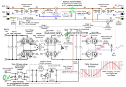
I adapted the Diagram to represent this exact use-case.
1669855144328.png
There is no PV. It's night! So let's keep it out of the game.
The AIO-Inverter triggered "Back to Utility" and "Low Voltage Cuttoff".
So AC-In Relay should be closed =>Load gets supplied from ACin.
Chgr Buck Switcher is open => So there should be no connection from Inverter to Battery.
So what in in this diagram under this configuration is pulling 1.5A or 70Watts.
I learned from you that in these AIO-systems Display and Controller are running on DC.
It can't be the display, this pulls maximum single digit Watts.
Is this really then the controller? But where is it connected if we would add it to the Diagram?
 
So what in in this diagram under this configuration is pulling 1.5A or 70Watts.
It is all the drivers (not shown in diagram) for power MOSFET's and IGBT's input gates switching at 20 kHz to 35 kHz rate, their body diodes reverse recovery switching loss, and PWM L-C filtering reactive current loss through sinewave H-bridge.

In standby mode, all these are shut down and not switching. You then still have uP, display, and coil power for pass-through relays.
 
Last edited:
My Must inverter consumes less but consumes about 7-10w, the solution is heat with the back to utility.

I was thinking of putting an external battery charger with a dri contact.
 
@RCinFLA @Mattb4
Thank you for all your patience and support.
But even after reading and reflecting all your posts, I must admit that things get clear for me only at the surface but it is still not 100% clear for me where those 70W or 1.5A idle current occure in my exact usecase.
So please allow me to dig a little bit deeper.

I adapted the Diagram to represent this exact use-case.
View attachment 122457
There is no PV. It's night! So let's keep it out of the game.
The AIO-Inverter triggered "Back to Utility" and "Low Voltage Cuttoff".
So AC-In Relay should be closed =>Load gets supplied from ACin.
Chgr Buck Switcher is open => So there should be no connection from Inverter to Battery.
So what in in this diagram under this configuration is pulling 1.5A or 70Watts.
I learned from you that in these AIO-systems Display and Controller are running on DC.
It can't be the display, this pulls maximum single digit Watts.
Is this really then the controller? But where is it connected if we would add it to the Diagram?

When your AIO switches to Utility, the inverter no longer supplies the loads but remains ready to take over in the event of an AC IN failure.

If you cut AC IN your AIO instantly switches to the inverter. The inverter is not ON not OFF but READY.

In this case, my AIO consumes 30W against 50W in normal mode.
 
@claus

It's possible to use SBU mode with the charger in Solar first mode.

In this case, when the AIO reaches the "bat 2 grid" voltage, it switches to Utility and at the same time recharges the battery up to the voltage of the "grid 2 bat" parameter, then returns to the batteries.

Otherwise set a "bat 2 grid" voltage high enough so that the battery can last another 24 hours and pray for the return of the sun. Clearly 70Wh in this mode is huge.
 
Hi,

I got the same problem, voltronic axpert vmIII twin my battery go down to 46V and inverterter throwing error 51 when batteries are low.
I have cutoff at 48V but inverter dont use utility even at cutoff i have to charge battery at solar only option.

To fix this i will use a simple power supply at 48V to charge battery at 48V but this should be integrated at inverter to use power until 48V and cutoff and use power from grid at 48V i dont want to charge from utility all the time battery because i want use low energy from grid
This option should be integrated, at 48V turn on power supply from grid so inverter have range 56V to 48V to use that for idle power consumption and switch to grid at 48V

There is a option:
Charger source piority
Solar first
Solar and Utility
Only Solar

When use only solar and have weak battery inverter in the morning will throw error 51 and use battery to the end of battery range not only to cutoff dc voltage range so its preffered dont use this option or use it with external power supply 48V directly connected to battery

I will test today other option Solar first and i will let know how its works
 
Last edited:
Nope on SUB mode inverter use 100W from grid its not good.
On SBU mode inverter is working on battery but cutoff low dc should charge inverter as well from grid, right now inverter use all power from battery until battery are flat.
Its a firmware bug or what?
 
It sounds like there is a setting off somewhere. One of the settings in yhere should basically be "at this voltage, start charging the battery from the grid" and if it's too low that will drain the battery below where the BMS cuts off before the inverter hits that "start charging" mode.
 
Back
Top