mrdavvv
Solar Enthusiast
- Joined
- Jan 14, 2020
- Messages
- 404
That's a lot of breakers
Nice design. I like your Visio diagrams.So this beast finally arrived:
View attachment 36504View attachment 36505
View attachment 36510
(8K LP1 US model) -- At a first glance i really like the quality of materials and the weight of it!.
- Planning on putting 10.5Kw of panels (26 x 405W), in a east - west configuration. Panels would be around 20 - 30° to E / W.
- Each MPPT would have 2 strings in parallel, with 6 or 7 panels each.
View attachment 36506
Also bought a little pylontech battery (2.2Kwh@48V), it should be able to communicate with the inverter trough CAN / RS485, this is against the DIY spirit.... but didn't have the 2 months to wait for the lifepo4 cells to arrive:
View attachment 36507
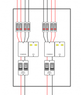
This would be the diagram of the full installation
Full Image Link
Ill keep posting here with updates during installation.
- What do you think?, any mistakes in the drawings?, any recommendations?.
With Growatt and MPP non isolated hybrids, both sides need to be fused/breaker. I had to use quite a few also. And then there is lightning protection, ground fault protection, AC side breakers, battery breakers, battery fusing,.... I think a whole house generator is much cheaper.That's a lot of breakers
Growatt? MPPT? I get what you’re saying.With Growatt and MPP non isolated hybrids, both sides need to be fused/breaker. I had to use quite a few also. And then there is lightning protection, ground fault protection, AC side breakers, battery breakers, battery fusing,.... I think a whole house generator is much cheaper.
Hello newbostonconst.
Thanks for your observations.
1.- Thats correct, i dont know if the diagram gives another impresion but thats the plan. 90% of our equipment its 120Vac, so the loads in the main panel are divided and balanced between the 2 phases.
2.- I see in the first diagram i didnt put the neutral in the critical panel, 2nd version is updated.
View attachment 38119
3.- Yes we are bonding at utility meter or main panel, one of the two.
4.- Got it.
5.- Service is less than 200A, but still considering multiple ground points just in case, as refered in new diagram. Grounding rods are >6ft apart.
6.- Critical loads panel is 12mt horizontal, and 5mt vertical from the main one. There is any rules about the point you mention?. Im not sure we can put a new ground near the critical load panel, as we would need to link together all the grounding scheme as that not possible in the building, we want to avoid the problems that filterguy mentions in here:
View attachment 38120
As i mention the installers also want to put a new ground rod for the critical loads panel and the PV system, but not sure how we can avoid the situation of the diagram.
Why did you parallel the strings of panels? Wouldn’t they be parallel at the MPPT’s if you just ran all 4 strings to the inverter? I’m gonna be doing a similar setup except with 20 panels (7s,7s,6s).

So it’s more convenient in your situation. I just thought I was missing something. Can’t wait to see the finish setup!Yeah the inverter has an integrated combiner, no matter what at the end you end up with 2 strings.
But in our situation was better to put them together higher up in the circuit so we can place only 2 sets of protections and switch's.. but i think both can be good.
View attachment 42968
Also you avoid having a bunch of thick cables near the inverter, only 4 for all your panels.


Just as a guess, if PV string is 299Voc and goes to 2V when connected to inverter, one possibility is polarity is reversed. Some inverters have a diode to clamp reverse polarity. No idea what error messages would be given, but check the polarity.
"over current" is surprising to me, since PV string can't deliver more than Isc. The MPPT can boost current, but it ramps up gradually.

 www.sunsynk.org
F20 DC over current fault of the hardware This is normally caused by the battery not being able to deliver email to current inverting needs. Overcurrent on the battery. To clear this fault you must focus on the battery and battery discharge settings. You need to check the C rating of the battery, can the battery provide the current your system needs you may have an 8 kW inverter but unless the battery can supply 8 kW it will simply crash out.
- Check the battery C rating
- Check the maximum discharge the inverter is set to
- On the controller check the maximum power inverter can supply this is a global setting you can see this on the main controller
- Check the battery cables are heavy enough to meet the demands
- Hi current overload on start up may also cause this causes fault

 www.sunsynk.org
Hope you solve it too!Inverter its live now!
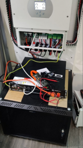
View attachment 45124
The internal rack mountings couldn't hold the battery weight, so i need to do some aluminum supports. Currently the battery is in the open, work in progress...
View attachment 45125
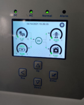
Currently using a 6 panel array (410W each), working as expected.
--------
Couple of problems.
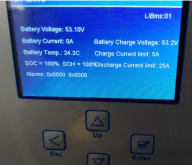
1) Battery BMS is recognized by both RS485 and CAN, but the charging data is incorrect (Should be 25A), need to check with the manufacturer:
View attachment 45126
2) When i connect the second array (7 x 410W), i get an instant error:
View attachment 45128
- Voltage is 299V at the main swith, at the moment you turn ON said switch, and PV goes to inverter, the voltage drop to 2V.
- Then inverter alarms about F20, and cannot work until i clear the fault.
Troubleshooting:
1.- Checked all cables on site, everything its OK, still need to check if all is good on the roof.
2.- According to the Sunsynk documentation, the error could be also caused by insuficient charging current capabilities at the battery, in a few words, i need more batteries.. Having only 1x2.4KWh (And incorrectly charging current detected by DEYE) .... this could make sense, however, i get the same fault while using the NO - Battery mode (Grid tie mode). Also im connecting most loads at the input, The critical load its only 500 - 800W. Not sure if charging current in the batteries are involved while the unit its working as string inverter.
3.- Checking with DEYE about this, they ask me to connect the Wifi module to troubleshoot.
Hope i can solve it!
Thanks for the advice, will do a good check in all the cabling from top to the last connector.
Check cables? Just put a DMM across the PV input terminals of inverter. Confirm polarity.

I'm glad it was a simple fix and definitely always double check!I was also thinking that i could have a bad crimp or a loose connection, so better to check it all and kill 2 birds... Altough if that was the case the inverter probably would trow a different code, related with AFCI or simillar.
But....
I did a quick check and found the problem... you were right! PV cables backwards, and you can even see it in this photo:

Deye / Solark 8K Setup, Some photos an diagrams!
Made a lot of progress this week, PV side its already installed, just need to work on the AC side. Also you can appreciate the size difference between the little 2.4kw MPP Solar vs the 8K Deye: Realy liked this ABB enclosure, very high quality and easy to work with:diysolarforum.com
So im kind of ashamed of making such a dumb mistake, but learned the lesson:
- Doesnt matter if you were waiting to turn on the system for weeks, doesn't matter if you are all excited!, double check everything.... everything! with calm.
Fail to mention that i almost toasted the inverter by connecting the battery backwards, but at least i noticed in time... like i said i wanted to turn it on before the sunset of that day!
The good side, inverter has half of my PV connected now, 5.3Kw.... today i saw it peak at 4.3Kw, and with that im making more energy that i need for now


