diy solar

diy solar

The "Meg" Build

As for the inverters themselves, turns out I am still having Inverter #1 kick onto bypass whenever a load higher than 3kw is applied. But if I remove the Grid Input, everything is perfectly normal. This is becoming a real PITA trying to diagnose, because the LV unit doesn't just TELL ME why its switching over to the grid??

Do you have equal lengths of wire for all your AC connections from each inverter (e.g. both L1's are the same, L2, Neutral)?
It might be interesting to measure the current draw of all your AC linens to make sure they're equally divided and that your neutral line isn't carrying more than you think.
 
Do you have equal lengths of wire for all your AC connections from each inverter (e.g. both L1's are the same, L2, Neutral)?
It might be interesting to measure the current draw of all your AC linens to make sure they're equally divided and that your neutral line isn't carrying more than you think.
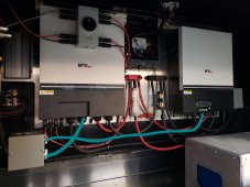
Hmm, no all the wires from Inverter #2 are about 2 feet longer. (In blue)

20210705_095231.jpg

They both join in the 6x6x4 junction box, where the legs go to the respective connections, and the neutrals/grounds all combine together.

Do you think this is causing fluctuations?
 
Yeah unless you use their ESS you can't QUITE do that.. but I've gotten close by using the conditional AC connection feature where it connects to AC only if, e.g., the battery SoC is below a certain threshold. The only other way I know is to not use a closed system (don't let the BMS control the Victron) and set the charge voltage of the SCCs higher than the Quattro's... lastly, it may be possible with Node Red ... One day I'll play with that stuff.. it's supposed to be awesome.

Ah, yes, what @K8MEJ posted

Cinergi, I don't have a Cerbo or RaspPi running VenusOS. Without something to tell the Multi/Quattro the system SoC (from my BMV), I don't think I can get it to automatically enable the AC charger when the SoC gets low. So the "easy" way via Virtual Switch may not work. I'll have to see if the ESS assistant can do it. I have the Bluetooth Smart Dongle on my MultiPlus and it's networked with the other chargers (MPPT) and BMV. Maybe there is a way for ESS to read SoC from the BMV via Bluetooth?
 
Hmm, no all the wires from Inverter #2 are about 2 feet longer. (In blue)

View attachment 55139

They both join in the 6x6x4 junction box, where the legs go to the respective connections, and the neutrals/grounds all combine together.

Do you think this is causing fluctuations?

I'm not sure if 2 feet is too much ... you may have current flowing in places you don't intend, especially if you're running L1 and L2 separately (one from each). I've lost track of your current AC wiring configuration. having their inverters powering their own legs (if that's what you're doing) is tricky given the need to bond ground and neutral. That's why I'd have them truly in parallel and connect both L1 and L2 to the same hot output (so no 240 capabilities). In any case, same length cables, especially for ground and neutral, is important. In this example, if they're both truly in parallel, and one is 1 foot and the other is 2 foot, then one will see twice the current as the other.
 
Cinergi, I don't have a Cerbo or RaspPi running VenusOS. Without something to tell the Multi/Quattro the system SoC (from my BMV), I don't think I can get it to automatically enable the AC charger when the SoC gets low. So the "easy" way via Virtual Switch may not work. I'll have to see if the ESS assistant can do it. I have the Bluetooth Smart Dongle on my MultiPlus and it's networked with the other chargers (MPPT) and BMV. Maybe there is a way for ESS to read SoC from the BMV via Bluetooth?

It can be set to use voltage, too .. IIRC .. so no VenusOS required (to communicate SoC).

ESS is Victron batteries only ... so unless you're using their batteries, I believe all the ESS features are N/A.
 
I'm not sure if 2 feet is too much ... you may have current flowing in places you don't intend, especially if you're running L1 and L2 separately (one from each). I've lost track of your current AC wiring configuration. having their inverters powering their own legs (if that's what you're doing) is tricky given the need to bond ground and neutral. That's why I'd have them truly in parallel and connect both L1 and L2 to the same hot output (so no 240 capabilities). In any case, same length cables, especially for ground and neutral, is important. In this example, if they're both truly in parallel, and one is 1 foot and the other is 2 foot, then one will see twice the current as the other.
Interesting.

I just put them back into parallel/split phase for the logs im going to be doing for MPP. I only seperated them because I thought that would keep them happy, but apparently not.

So now they are in split phase again with communication, how do I check if essentially one is backfeeding the other? Or should I just get some wire and cut it so they are at the same length?

I can put them in parallel/single phase with a little more work/rewiring, the MPP units even have a "current sharing" cable so they will balance each other.
 
I'm not sure if 2 feet is too much ... you may have current flowing in places you don't intend, especially if you're running L1 and L2 separately (one from each). I've lost track of your current AC wiring configuration. having their inverters powering their own legs (if that's what you're doing) is tricky given the need to bond ground and neutral. That's why I'd have them truly in parallel and connect both L1 and L2 to the same hot output (so no 240 capabilities). In any case, same length cables, especially for ground and neutral, is important. In this example, if they're both truly in parallel, and one is 1 foot and the other is 2 foot, then one will see twice the current as the other.
I think you might be onto something, I am currently logging on my computer and I was watching the MPP screens when I turned on a 3rd AC (which is hooked to inverter #1), and I saw inverter #2s output spike from 1.2kw to 4kw, then the transfer to Grid happened and the output dropped to 2-300watts, then slowly climbed back to 1.3kw. Its gotta be the wiring somehow.

EDIT: Nevermind, I must be seeing things, because I cant replicate it now.
 
Last edited:
I found a setting called "Overload Bypass" and disabled it on both inverters. Now its working great?? Lol I'm pulling my hair out.

I also measured voltage between the 2 legs and neutral. Both outputting exactly 119.5v to neutral and exactly 239v between the 2 legs. Now I don't have an oscilloscope, but that should mean they are pretty much in perfect 180* sync correct?
 
Check this out: Virtual Switch Ignore AC - Victron Community - Victron Energyhttps://community.victronenergy.com › attachments

Warning: it wants to download a PDF file. But it tells us one way to do this. I'll see if I can get this working this afternoon.

Dan, hopefully you can your current system setup and working as you expect. But in the off chance you want to look into Victron gear I can tell you with 100% assurance that you can set PV prioritization via several different means. Currently, I don't have the means to synchronize SoC across all devices, most importantly the inverter/charger/transfer switch. I've been wanting to get a Cerbo GX anyway so this is just another reason to get it. Without it, right now, I have it set to prefer DC input only (PV and/or battery) and only accept shore power if one of the following conditions occurs:

  • The inverter outputs more than 2500 watts for at least 30 seconds and releases when AC load fall below 1000 watts for 2 minutes
  • Vdc falls below 12.00 volts for at least 60 seconds - then shore power is accepted until the AC charging system finishes bulk charging for 3 minutes
This is via the "easy" method. With the ESS assistant there are more fine-grained controls but I haven't tried that yet. Maybe once I get a Cerbo....

Anyway, I didn't mean to hijack your thread, but your question spurred me to figure out how to get it set up on my Victron system. This will help when my wife plugs her car directly into the RV to charge it and sucks my RV battery dry because usually I don't plug the RV in. Now I can plug it in and still let it prefer PV power when it's available.
 
yeah you've got split phase going & verified now. As for the line lengths ... there's still a chance you've got current flowing where it's not supposed to (but less likely in a split-phase setup). Would need to know where you combine ground (or if you daisy-chain it); Also, where is your ground-neutral bond happening when you're not connected to grid?
Do you have a clamp meter to verify various paths of current? (hopefully there's room in the combiner box to get it around individual wires)
 
Dan, hopefully you can your current system setup and working as you expect. But in the off chance you want to look into Victron gear I can tell you with 100% assurance that you can set PV prioritization via several different means. Currently, I don't have the means to synchronize SoC across all devices, most importantly the inverter/charger/transfer switch. I've been wanting to get a Cerbo GX anyway so this is just another reason to get it. Without it, right now, I have it set to prefer DC input only (PV and/or battery) and only accept shore power if one of the following conditions occurs:

  • The inverter outputs more than 2500 watts for at least 30 seconds and releases when AC load fall below 1000 watts for 2 minutes
  • Vdc falls below 12.00 volts for at least 60 seconds - then shore power is accepted until the AC charging system finishes bulk charging for 3 minutes
This is via the "easy" method. With the ESS assistant there are more fine-grained controls but I haven't tried that yet. Maybe once I get a Cerbo....

Anyway, I didn't mean to hijack your thread, but your question spurred me to figure out how to get it set up on my Victron system. This will help when my wife plugs her car directly into the RV to charge it and sucks my RV battery dry because usually I don't plug the RV in. Now I can plug it in and still let it prefer PV power when it's available.
I will do my best to get these MPP units working, but my last ditch effort will be to attempt to return them and buy Victron equipment. We'll see.

yeah you've got split phase going & verified now. As for the line lengths ... there's still a chance you've got current flowing where it's not supposed to (but less likely in a split-phase setup). Would need to know where you combine ground (or if you daisy-chain it); Also, where is your ground-neutral bond happening when you're not connected to grid?
Do you have a clamp meter to verify various paths of current? (hopefully there's room in the combiner box to get it around individual wires)
All of the combined grounds are in the junction box on the left, along with where the neutrals are all joined together as well.

I'm pretty sure the neutral and ground are bonded internally. I remember getting continuity between the neutral/ground right at the machines input/output.

It is pretty cramped in that box, but yes I can get my clamp meter in there. Should I put a load on just one machine and check to see if power is being backfed to other? Or checking to see how much current the neutral is carrying?

Thank you for all the help guys!!
 
I'll assume you have 1 common N running to the breaker box.
Let's get readings from G, L1, L2, and the common N. Also readings from the N's going to each inverter. Do that with loads on both L1 and L2.

Is the Air Conditioning the only thing that can cause the problem?
 
@Lt.Dan on a separate note, do you know the CFM of the ventilation you tried earlier? I just received a new 4" vent fan with twice the CFM and it's doing a much better job at getting air into the compartment. I don't yet know if that's enough ... I'm also considering taking the 9k cassette I'm upgrading and putting it in the basement ... totally overkill .. will discuss with the LG tech next week.
 
I'll assume you have 1 common N running to the breaker box.
Let's get readings from G, L1, L2, and the common N. Also readings from the N's going to each inverter. Do that with loads on both L1 and L2.

Is the Air Conditioning the only thing that can cause the problem?
I'll try and get these today, and yes, the AC is the only thing with enough surge i think to trip it.
@Lt.Dan on a separate note, do you know the CFM of the ventilation you tried earlier? I just received a new 4" vent fan with twice the CFM and it's doing a much better job at getting air into the compartment. I don't yet know if that's enough ... I'm also considering taking the 9k cassette I'm upgrading and putting it in the basement ... totally overkill .. will discuss with the LG tech next week.
I had 1x 4" 125cfm pulling air from the interior and another 4" 125cfm pulling air out of the compartment to atmosphere. It never got under 5* under ambient outside though. Even the 5000BTU window AC thats in there now runs quite a bit! Its maintaining a nice 72*F.
 
I had 1x 4" 125cfm pulling air from the interior and another 4" 125cfm pulling air out of the compartment to atmosphere. It never got under 5* under ambient outside though. Even the 5000BTU window AC thats in there now runs quite a bit! Its maintaining a nice 72*F.

I'm trying this out now (195 CFM) https://www.amazon.com/gp/product/B01M7S46YZ ... the one I tried previously was 106.
I wonder if sucking the air out was inadvertently pulling in warm air from somewhere else.
I'll let you know how it goes. I also wonder if directly routing the air to the inverter intakes (in your case) would work.
 
I think pushing cold air from your climate controlled space into the inverter would provide the most cooling.
That fixes the concern of sucking in hot outside air and "carburetor heat" recirculating what the inverter just heated.
 
I believe that's true, pumping cold air directly into the intake of the inverter would work best. On the LV6548, it has 2x intakes per inverter, and plumbing forced air to each one might be a little difficult because of the way it would mount to the chassis and such. But definitely the best way.
 
System has been working flawlessly that last 2 days, but im still bugging to atleast get them on the same firmware version.

Battery is fully charged by 1:30pm today, from totally dead at 6am. I guess I need more battery... lol
 
System has been working flawlessly that last 2 days, but im still bugging to atleast get them on the same firmware version.

Battery is fully charged by 1:30pm today, from totally dead at 6am. I guess I need more battery... lol
Or more efficient air conditioners. Pick your poison. A 3-headed mini-split is in your future.
 
Or more efficient air conditioners. Pick your poison. A 3-headed mini-split is in your future.
I'm trying to hold off as much as I can ?? this won't be my permanent residence so I'm trying not to do TOO much work for something I'm not going to use long term. I know super contradictive to what I've already done ???

I do plan on keeping it long term, but just using it for vacations/trips. Maybe 20 times a year.
 
Back
Top