diy solar

diy solar

The "Meg" Build

I haven't been able to. I've tried doing it all this week, but I got really sick on Tuesday and have been a little incapacitated. I got tested for the 'Rona yesterday so we'll see, but im already feeling much better. I was planning on getting out there tonight when it cools off a bit, but it might be early tomorrow morning.

Hope you get well! This Delta variant is kicking a lot of asses for 2 to 5 days it seems,
 
Hope you get well! This Delta variant is kicking a lot of asses for 2 to 5 days it seems,
Thanks! I got my test results back today, Negative! I must've got hit with something else, but I am feeling much better today, so im thankful for that!

I did install the cap last night, and then got to play with it today, and it is a whole lot better, but it still acts like its sticking every once in a while. Difference is, the voltage doesn't drop so low that it shuts off all the 12v equipment (like the OneControl system, the router, etc). So if it sticks, then I reverse the direction for a second, and it starts working just fine.

I'm going to experiment a little bit with bigger gauge wires and apply the cap directly at the circuit breaker that controls the pump, maybe it will help.
 
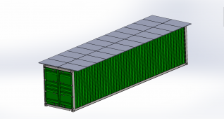
I'm setting up my array to fit on my new shipping container... trying to decide if the option to set tilt for the season is worth the extra effort. In December, I gain 1 extra hour, from 2.28 hours to 3.26 hours (according to a solar irradiance calculator). In the summer, flat is best based on the calculator.

I can fit an exact 24 panels, for 2x 6s2p, which is exactly what I have. It was meant to be lol

Solar Panel Array.png
 
With hydraulics to lift about 1500 lbs?
Or poles, cables, crank to lift and a way to secure them?
Pipe down the middle, so tilts where balanced?
All without welding.

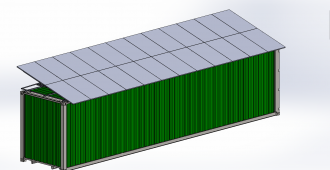
For tilt, I think put the fulcrum and middle of array along one top edge of the container. Then it is either flat over the top and sticking out, or vertical on the side and sticking up.
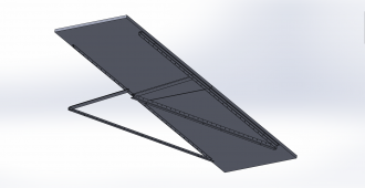
I didnt want any complicated or excess parts. I always try to KISS it. So there is actually an individual Tilting mechanism for each vertical pair. All of these "Pairs" are bolted to 3x sets of unistrut that runs the length of the containter (120' total). This keeps the weight down to about 85lbs each assembly and should be manageable with one person i think. No welding, just a few 3/8" Bolts. Everything made out of 1/8" Aluminum. The pivot point at the bottom is positioned exactly to where, if the panel is 90* (completely vertical), the panel will touch the side of the storage container, and when at 0* (completely flat or horizontal) then the panels are centered over the container.

I'm also curious if this will be road worthy if picked up by a semi for transportation. I plan on using 16x huge 100lbs Neodymium magnets to hold it down onto the container. I wont know until i get the entire system installed and see how hard it is to lift off of the container, and worst case scenario, I have to add more magnets, or run a few heavy duty straps over them to keep from lifting.


(Pictured is at 15* of tilt)
Individual Tilt.png
 
purchasing one right now is not feasible due to market value in them. I do have the option of purchasing the container from them, and at that time I just pay the current market value for the container, so if its cheaper in a year, ill drop the cash
Curious.
What is your source asking retail for that? I haven’t looked recently but in the northeast they used to to be ~$2250 for a 20 and ~$3000/3500ish for a 39.
(No prices online anymore it seems)
 
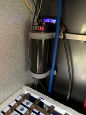
+1 for adding a capacitor to the load side of the Daygreen. I have the 13.8v 30a model (A4D13R8C30) and was seeing similar flickering issues when the water pump kicked on and especially when using the tongue jack. Installed a 1farad cap and dimming/flickering issues went away. Inductive loads are difficult for the DC converters to handle.
24C4959C-1556-4716-9810-E0389A66D867.jpeg
 
Thanks! I got my test results back today, Negative! I must've got hit with something else, but I am feeling much better today, so im thankful for that!

I did install the cap last night, and then got to play with it today, and it is a whole lot better, but it still acts like its sticking every once in a while. Difference is, the voltage doesn't drop so low that it shuts off all the 12v equipment (like the OneControl system, the router, etc). So if it sticks, then I reverse the direction for a second, and it starts working just fine.

I'm going to experiment a little bit with bigger gauge wires and apply the cap directly at the circuit breaker that controls the pump, maybe it will help.

I would get the cap connected as close to the hydraulic pump and control solenoids with large gauge wire.
 
Inductive loads are difficult for the DC converters to handle.
The lingering few seconds of inductive loads may be a ‘converter problem’ but the initial drop, spike, and flutter can also happen on direct connection equivalent voltage power from a battery (bank).

An oscilloscope read of what happens when a load is applied to a line will reveal some interesting ’reactions’ to voltage when the samples per second is high and plotted on a curve. It’s the same kind of thing that burns out radios, stereos, and sonar on a boat when one turns the key engaging the starter motor; an event of high voltage occurs both when the key is engaged to ‘start’ position and then again when released from ‘start.’ The release is the more violent but shorter in duration.

I’m no EE but in this case I think that while the capacitor will work for what is basically buffering while the electronics react to the sudden load- inductive or otherwise- it is masking what happens electrically. Probably figuring out how to isolate lights vs. motor loads is the best approach even if a capacitor is used.
Like I said I’m no EE so someone with engineering background can probably confirm or destroy this information- I’ve never seen a scope reading from a power-on event with a power supply/ converter. I was just reading this and this clicked on some brain cells about inrush spikes from boat experience.

Of course a small 48V to 12V sized for the lights and other constant loads and a bigger converter (cap is likely still needed) for the transient high power loads would be best.

But when retrofitting existing RVs it can be tough to do this separation as they tend to run shit all over the place that is not easy to get to.
 
Last edited:
Curious.
What is your source asking retail for that? I haven’t looked recently but in the northeast they used to to be ~$2250 for a 20 and ~$3000/3500ish for a 39.
(No prices online anymore it seems)
I'm in Cali, and we "apparently" have a huge shipping container shortage. Now i work in a sheet metal shop, where we process millions of pounds in Stainless Steel a year, and getting material in the last 6 months has been very difficult, and every one of my suppliers has told me its because of the shipping problems from China, etc. I've had a few of them tell me that China is hoarding all these containers but idk if its true, or why.

Anyways, to answer your questions, a 20' container is roughly $2500 here, and a 40' can be anywhere from $5-6000. Last year they were less than half of that.
 
Curious.
What is your source asking retail for that? I haven’t looked recently but in the northeast they used to to be ~$2250 for a 20 and ~$3000/3500ish for a 39.
(No prices online anymore it seems)


I hear there are a bunch of them floating in the ocean. Maybe you can tow one home.

1627825218788.png

 
The lingering few seconds of inductive loads may be a ‘converter problem’ but the initial drop, spike, and flutter can also happen on direct connection equivalent voltage power from a battery (bank).

An oscilloscope read of what happens when a load is applied to a line will reveal some interesting ’reactions’ to voltage when the samples per second is high and plotted on a curve. It’s the same kind of thing that burns out radios, stereos, and sonar on a boat when one turns the key engaging the starter motor; an event of high voltage occurs both when the key is engaged to ‘start’ position and then again when released from ‘start.’ The release is the more violent but shorter in duration.

I’m no EE but in this case I think that while the capacitor will work for what is basically buffering while the electronics react to the sudden load- inductive or otherwise- it is masking what happens electrically. Probably figuring out how to isolate lights vs. motor loads is the best approach even if a capacitor is used.
Like I said I’m no EE so someone with engineering background can probably confirm or destroy this information- I’ve never seen a scope reading from a power-on event with a power supply/ converter. I was just reading this and this clicked on some brain cells about inrush spikes from boat experience.
I have my BSEE with 27 years experience in power distribution. The voltage dip on “start” and spike on “release” is characteristic of an inductive load. An inductor is basically just a coil of wire, which generates a magnetic field when current passes through it. When voltage is initially applied, the inductor is essentially a direct short until the magnetic field is generated. This is what causes the voltage dip during “start”. On “release”, the opposite happens. The inductor acts as the energy source until the magnetic field collapses, resulting in the spike you describe.
 
Inductive loads and motor loads are a bit different.

With an inductive load (e.g. 1 Henry in series with 1 Ohm), the current is drawn out of phase with voltage, and inverter has to accept current driven back into it part of the cycle. Total Volts x Amps it has to deliver is greater than actual Watts, so inverter needs to be oversized.

An amplifier (inverter) has to be designed to be stable with reactive (inductive and capacitive) loads. Often amplifiers go unstable with loads that move to far into other I/V quadrants. Some inverters will be better designed/tested than others.

Motor loads have an initial current of Locked Rotor Amps, about 5x running load. Inverter has to supply that for about a second more or less. So does the battery, so voltage drop on cables at high current matters. Large capacitor can help. While stalled the motor would look like an inductive + resistive load. Running it could be something different. I've seen funny current waveforms (like triangle, not sine wave) from my A/C.

The grid is so massive it can generally handle all that, and has rotating generators. Wires need to be thick enough.
 
I did finally get my hands on a 40' shipping container.


So since its a rental, I can't put any holes into it, and im looking into PV mounting systems that don't penetrate, and im thinking more and more about magnets ?
Think about "pipe clamps." Or, at least the concept. Position a piece of unistrut (or some other long piece) across the 8' width on top of the container. Then, extend a piece of something downward at each end of the unistrut. Think of an open "C" facing downwards. Then some screw-type devices to "clamp" each end of the "C" to the sides of the container. Maybe also around the top edges?

Multiple "clamps" would be positioned on the top of the container. This should give you a strong, stable "foundation" assembly. Then, mount whatever you want to the unistrut assembly.

No holes in the container. It would be a mechanically-fastened system that might be stronger than magnets, especially going down the highway.
 
Shipping containers have these standardized oval cut outs at each corner of the cube. They are used to hold them to the stack on the he ship, for picking up with a crane, and holding it down to the trailer chassis. It would be much easier (and plenty strong enough) to tie into those on each corner and then magnets down the long side for extra stability.
 
Back
Top