diy solar

diy solar

Testing my Valence U27-12XP

Cliffman

New Member
Joined
Oct 30, 2019
Messages
45
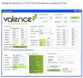
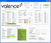
I have 4 hooked in Parallel. Go Power IC-3000 Inverter. Putting a 62 amp load for about 1.5 Hours. Note the "State of charge" and the "Module Voltage" on Module 1 compared to Module to 2. Can anyone explain this. Thanks!
 

Attachments

  • Low SOC.jpg
    Low SOC.jpg
    107.5 KB · Views: 102
  • Good SOC.jpg
    Good SOC.jpg
    106.5 KB · Views: 94
Results of my test today. I was only able to get 4 hours at 62 amps. That's only 248 AH by my calculation. That's IS disappointing since I have a total of 552 AH and assuming I'm going to pull it down to 20% that leaves 441.6 USABLE AH! I had my low voltage cutoff set at 11.00v. Not sure how much more I could have gotten if It was at the default setting of 10.5. Now that said I have read about a "Theory" (Can't recall the name" where the higher the amp draw the less AH you'll get. But I don't know enough about this stuff to know if my constant 62 amp draw is affecting that.
 
I was able to run a 32 amp load for 3.5 hours on a single battery (100% SOC down to inverter shutoff), so something may be off with your setup. Granted, higher amp loads will alter the overall capacity a bit, but 62 amps in a 4p setup isn't that much in the grand scheme of things. Are all the connections/cables room temp during the test? Anything that's hot is wasting capacity. What sort of cables are being used to connect the batteries? I was surprised at how much heat is generated at a loose connection. To eliminate components, I would disconnect all the batteries. Charge each one individually, then run a load on it while logging the battery data with the Valence software. Repeat for the rest of the batteries. Then go through the logs to see if you have cells loosing voltage or gaining temp at faster rates over the duration of the test. I would also take note of what the WH DSCHG numbers are at the start and end for each battery. That gives you what the BMS thinks it's delivered. If the number you're getting from the BMS and the one you calculate from the actual run time at a given load, are way off, it's time to be looking at the components of the system. Having a current shunt or coulomb counter would be a good way to verify the numbers off the BMS and the amp draw.

The SOC from the internal BMS will calibrate itself after a couple of 100% to 20% to 100% discharge and recharge cycles. Keep an eye on that to verify.
 
Based on the attached capacity chart from Battle Born 13.2 is 70% and 13.1 is 40%. My starting voltage was 13.16 which is what... 50-60 %? That explains ALOT! So I started my test with batteries at maybe 60% charged. Based on that I should have pulled 324 AH's if I went to 0 which is 10 Volts. I had my cutoff set to 11 which is somewhere in the 5% remaining range? I was able to pull 62 amp for 4 Hours so that's 248 AH's. The starting voltage is a guess so I might be right in there as far as usable AH's. The elephant in the room is WHY SUCH A LOW STARTING VOLTAGE??? From what I have read holding lithium batteries at full charge is not good for them. so what is the sweet spot? 70% (13.2v)? That means we loose 30% of the battery capacity right off the bat. IMO that is HUGE! So my 135 AH battery now becomes a 94.5 AH battery and now my range is from 70% to 5% that leaves 65% of battery usage. WOW! someone please tell me I'm WRONG!
 

Attachments

  • Charge Capacity.JPG
    Charge Capacity.JPG
    35 KB · Views: 43
Last edited:
Mine show 13.49v at 99.6 SOC. Something definitely not working right on the charging side or the batteries have weak cells that prevent the pack from getting to full voltage.
 
Mine show 13.49v at 99.6 SOC. Something definitely not working right on the charging side or the batteries have weak cells that prevent the pack from getting to full voltage.
Is this unhooked from charger and all other loads? Is the voltage and SOC from the Valance software? What is your charging parameters? Bulk and Float?
 
Last edited:
I have 4 hooked in Parallel. Go Power IC-3000 Inverter. Putting a 62 amp load for about 1.5 Hours. Note the "State of charge" and the "Module Voltage" on Module 1 compared to Module to 2. Can anyone explain this. Thanks!
Did you make your own cable connector or did you buy the diagnostics toolkit?
 
I have three of these U27-12xp wired up and just did another capacity test the other day on them. I have a magnum 2000 watt inverter/charger set on 13.8V float (suggested setting per the manual from Valence). With about a ~60amp discharge load on them I got 368AH out of my three until my inverter shut off(11.3V is my setting).. which is about 120ah per battery. I am happy with that. I think if you are using a quality charger and make sure they are good and float charged to 13.8V and not accepting anymore current at that voltage, they are full and you will get a good test of capacity.

John
 
So just to clarify, because I see people saying this has been answered before, but i'll be a monkey's uncle if I'm seen a clear cut answer about it. Can I use 10 of these U27-12XP Batteries without damaging them or sacrificing their cycle life with them in parallel without any issues? I do NOT have the external "U-BMS'-LV" unit I keep hearing that their internal BMS's will be able to manage this bank fine because each battery has a BMS and then because they're in parallel, they'll balance each-other. I have also made a cable to the USB 485 and have version 12.12 of the software. Am I understanding this correctly or am I about to pay $3250 and get something I can't use like I think I can??
 
Hmm, very... interesting -- I saw that last night digging like a mad-man... It doesn't say if it has software with it or how exactly you would connect that to the victron multiplus.. Guess I'll call the guy in the morning and see what he says..
 
So just to clarify, because I see people saying this has been answered before, but i'll be a monkey's uncle if I'm seen a clear cut answer about it. Can I use 10 of these U27-12XP Batteries without damaging them or sacrificing their cycle life with them in parallel without any issues? I do NOT have the external "U-BMS'-LV" unit I keep hearing that their internal BMS's will be able to manage this bank fine because each battery has a BMS and then because they're in parallel, they'll balance each-other. I have also made a cable to the USB 485 and have version 12.12 of the software. Am I understanding this correctly or am I about to pay $3250 and get something I can't use like I think I can??
What is your application? RV with DC draw or Home with AC Only? These batteries where designed for Series connections and that's what the external BMS is for. If you're hooking all in Parallel and no DC draw (home use) then IMO you don't need the external BMS. If you are using them in an RV and have a DC draw then you have the potential (however remote) of pulling them down below there safe voltage if your inverter shuts down at the Low Voltage Cutoff setting. In that application the external BMS will shut off any draw at the Low voltage Cutoff. Sorry, there is just no straight forward answer. If you can afford it and want to play it safe get the 500.00 BMS.
 
If it was me I'd just get the batteries, check'em out for same voltage then decide on the BMS
 
What is your application? RV with DC draw or Home with AC Only? These batteries where designed for Series connections and that's what the external BMS is for. If you're hooking all in Parallel and no DC draw (home use) then IMO you don't need the external BMS. If you are using them in an RV and have a DC draw then you have the potential (however remote) of pulling them down below there safe voltage if your inverter shuts down at the Low Voltage Cutoff setting. In that application the external BMS will shut off any draw at the Low voltage Cutoff. Sorry, there is just no straight forward answer. If you can afford it and want to play it safe get the 500.00 BMS.
I'm using one of these in a travel trailer... Should I be adding a battery protect or some relay switched on mppt's load terminals to prevent over discharge? Is it pooched if it drops to 10v or whatever? Thanks.
 
So just to clarify, because I see people saying this has been answered before, but i'll be a monkey's uncle if I'm seen a clear cut answer about it. Can I use 10 of these U27-12XP Batteries without damaging them or sacrificing their cycle life with them in parallel without any issues? I do NOT have the external "U-BMS'-LV" unit I keep hearing that their internal BMS's will be able to manage this bank fine because each battery has a BMS and then because they're in parallel, they'll balance each-other. I have also made a cable to the USB 485 and have version 12.12 of the software. Am I understanding this correctly or am I about to pay $3250 and get something I can't use like I think I can??
Putting in parallel should be fine. There was a thread some months ago that covered this in more detail. It has basic features inside. the external bms seems to be for large parallel/series installations. Its hard to find documentation because the company was sold and the website changed again

Also,
Based on the attached capacity chart from Battle Born 13.2 is 70% and 13.1 is 40%. My starting voltage was 13.16 which is what... 50-60 %? That explains ALOT! So I started my test with batteries at maybe 60% charged. Based on that I should have pulled 324 AH's if I went to 0 which is 10 Volts. I had my cutoff set to 11 which is somewhere in the 5% remaining range? I was able to pull 62 amp for 4 Hours so that's 248 AH's. The starting voltage is a guess so I might be right in there as far as usable AH's. The elephant in the room is WHY SUCH A LOW STARTING VOLTAGE??? From what I have read holding lithium batteries at full charge is not good for them. so what is the sweet spot? 70% (13.2v)? That means we loose 30% of the battery capacity right off the bat. IMO that is HUGE! So my 135 AH battery now becomes a 94.5 AH battery and now my range is from 70% to 5% that leaves 65% of battery usage. WOW! someone please tell me I'm WRONG!
Dont use the voltage to determine soc. Its too difficult. Charge till full with bench power supply, then discharge to 11.5v and use a large shunt for the test.

But please, do not use voltage to determine initial state of charge. There can be voltage drop inside etc. It has a shunt as well. Dont use voltage.
 
I'm using one of these in a travel trailer... Should I be adding a battery protect or some relay switched on mppt's load terminals to prevent over discharge? Is it pooched if it drops to 10v or whatever? Thanks.
To be on the safe side I'd say yes but in my application which is 4 of the bats hooked in parallel I'm happy with just my inverter set at 10.75 LVCO
 
Back
Top