diy solar

diy solar

So... Set me straight on a few things related to battery C ratings and BMS capacity... Please!

BillCaswell

New Member
Joined
Jan 10, 2020
Messages
78
Hello all,
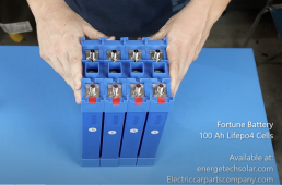
The Fortune 100Ah 3.2V 6C battery cell has been receiving good recommendations around the internet including on the Will Prowse DIY Solar Power YouTube channel. Checking the specs on the website www.electriccarpartscompany.com website lists some of the specs as "2C (6C for 10 seconds)." I am having a hard time finding a BMS that will work at 600 amps. Any suggestions?


A little back ground. I am replacing the 8D size, 24 volt AGM battery house bank system that is 2S/2P consisting of 12volt batteries from my sailboat. The house bank is also used to run the 20hp bow thruster electric motor. Typically the bow thruster is used in 3-5 second bursts. My challenge is that the running current is approximately 600 amps with an inrush current of 2-3x 1200-1800 for a few tenths of a second. For reasons that have to do with how the boat is configured, I need to keep powering the bow thruster using the house bank. See below for a picture of the battery box (basement) that I have to work with.

I have room in the battery box for 96 of these Fortune 100Ah LFP cells. If this helps, the battery box is

Battery Box
L: 47 1/4” (1,200.15 mm)
W: 22 1/4” (565.15 mm)
H: 21” (533.4 mm)


I am still working out how to organize the cells but could use any arrangement that provides 24 volts.

Two questions:

(1) Is there a recommendation on how to arrange the cells?
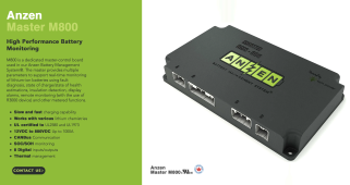
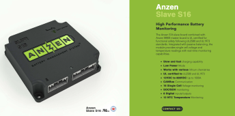
(2) Which BMS(s) do you recommend I look at? It needs to support the 6C pull for 10 secs.

Sources of charging include engine driven 220A Balmar alternator, 17.5 kWh generator and soon 1,000 watts of solar.

Thanks in advance. I hope that asking these types of questions are in bounds for this forum thread?

Screenshot 2022-11-25 at 23.39.09.png


Screenshot 2022-11-25 at 23.38.37.png
IMG_6503.jpeg
 
A bit of a typo in my earlier post. Here are the specs. The cells have a Max Pulse Discharge Current of 500A (<5 sec). Assuming that 96 cells properly arranged will support this usage including the momentary inrush current to start up the bow thruster motor.

Thanks again for taking the time to review my posts!

Screenshot 2022-11-26 at 00.24.03.png
 
Last edited:
What I think I need to find is a BMS that uses contactors and not use mosfet switches to limit current flow. Yes? No?
 
8S 12P battery configuration
12P x 200A(2C) = 2400A (continuous)

Note: busbars are only rated for 150A so 12P x150 = 1800A (continuous)

I agree with using a contactor BMS
Be sure to configure your continuous current on the BMS to 15% above what you need.
JK makes a 1000A contactor BMS but not sure how it will do in a marine environment.
 
I am chatting with a very experienced battery system designer and electrical engineer.

He says that he has built some marine systems that use Super-LTO cells from Toshiba that can discharge up to 100C used to start diesel engines. I've enclosed picture of the last generation Super-LTO cell.

That has me thinking about whether it's possible to build a mixed battery chemistry house bank – LFP and LTO.

Meaning that I would have a small bank to power the bow thruster given that I am only using it in short 5-10 second bursts. Then it would quickly re-charge it from the LFP bank, generator, alternator etc.

I have no idea if this is possible or advisable. I do not believe that an entire house bank of LTO batteries makes sense as I'm told that they are better for high demand over relatively short periods. And they are expensive.

I would have the larger LFP to run the rest of the boat electrical demand.

Having a mixed chemistry house bank in my opinion is conceptually no different than what I will have with LFP for the main house bank, and AGM lead acid at 12 volts for the generator battery, and 24 volts AGM for the main engine. I will just remove the AGM house bank and replace with a split system. One smaller battery bank to drive the bow thruster and a larger system to power the rest of the boat.

I need to think about how to keep everything charged correctly. I've asked my engineering colleague what BMS is used for the Super-LTO cells and will post his answer here.

Happy to hear what others think.
 

Attachments

  • image003.jpg
    image003.jpg
    38.3 KB · Views: 5
8S 12P battery configuration
12P x 200A(2C) = 2400A (continuous)

Note: busbars are only rated for 150A so 12P x150 = 1800A (continuous)

I agree with using a contactor BMS
Be sure to configure your continuous current on the BMS to 15% above what you need.
JK makes a 1000A contactor BMS but not sure how it will do in a marine environment.
The 10 second burst current would be 600A x 12 strings = 7200A
 
8D’s can deliver incredible current reasonably inexpensive. It may be cost effective just to replace them, and they provide a bit of ballast too LOL. By the time you create a Lifepo4 equivalent with appropriate current and charge upgrade requirements you’d be four to six times the cost. Also a DIY battery on an insured marine vessel may void coverage even if they are unrelated to a fire. Insurance companies look for anyway not to pay out.
 
8D’s can deliver incredible current reasonably inexpensive. It may be cost effective just to replace them, and they provide a bit of ballast too LOL. By the time you create a Lifepo4 equivalent with appropriate current and charge upgrade requirements you’d be four to six times the cost. Also a DIY battery on an insured marine vessel may void coverage even if they are unrelated to a fire. Insurance companies look for anyway not to pay out.
With my 12 volt 8D AGM batteries 2S2P, I have a theoretical 510 ah capacity, with 50% or 255 ah usable. My goal >1,000 ah. Which is why I'm chasing the LFP/LTO solutions with its storage capabilities and quick ability to charge via the generator, engine driven dedicated Balmar alternator, and solar. I am working on my two year plan to launch an around the world circumnavigation. I have checked with my current insurance underwriter and carefully read my policy. At this point, there are no restrictions.

With that said, I am working with (and being coached by) an engineer that has significant experience building electric propulsion and energy storage development (Li-ion, NiZn, Li-S, Al-ion, metal-air, graphene supercapacitors) storage system for both commercial and military applications, etc. He is encouraging me get my feet wet and is providing some guidance along the way as I work to come up to speed.

I'm not dismissing the possible issues with insurance underwriters. This is why I am paying attention to the ABYC standards work and looking for UL listed and certified components. I am slightly nervous to be honest, but want to focus on good engineering design and high quality components.

Thanks for the comments. I am very much in learning mode and am trying glean as much as possible from the many on this forum that have successfully engineered and built battery systems.
 
I think you’ll get there. Test the crap out of it before you bring it in the hull. LFP/LTO are proven reasonably safe chemistries. Always be thinking “what if”.
 
I searched on the DIY.. forum for metal (alum. or SS) battery cases. Not much luck. Does anyone have a link to a good selection of battery boxes?
 
I think you’re going to have to them fabricated. I say “them” because two or more will be easier to lower into its final location then run jumpers across as needed but make sure if in series the the jumper’s resistance equals the resistance of a buss used. You can have the boxes hard anodized as a secondary measure of insulation(accidental contact). You can tell the plater that they can anodize one half at a time if their bath isn’t deep enough became aesthetics isn’t the primary function. Sheets of Formica can be used for the to line the interior of the boxes and slipped between the cells. Remember to incorporate room for the bms and a method of mounting it. A flange around the top will allow the attachment of a cover. Pem nuts can be installed in the back side of the flange AFTER anodizing. A hard foam gasket can be used on the flange to seal out most of the salt laden air. A cover could be fabricated from epoxy sealed .42” “HardieBacker” that would be fire resistant and allow Wi-Fi communication with the bms. A method of safely (insulated) retaining the cells within the box and a battery box hold down is mandatory by USCG regulations. Use a quality non metal filled antioxidant like NO-OX-ID “A-special” ,Non lithium based winch grease, “Green grease” or silicone dielectric grease on the cell buss/terminal contact points but not on the thread because it will greatly increase the tension on the fastener due to the reduction of friction when torqued. Do not use non electrical grade silicone (acid based) to seal wire openings. If it smells like vinegar it shouldn’t be anywhere near electrical. It out gasses a corrosive substance for months. Grommets for large wire openings can be fabricated from a hose split down the side. Electrical grade silicone is probably the best to seal pass throughs, 3M 5200 and “Shoegoop” are acceptable but near impossible to remove/adjust the wire later. I hope this gives you some ideas.
 
Last edited:
for what it is worth, oshcut has served me well for laser cut stainless steel sheet. they support bends as well. recently had two circular plates of stainless steel laser cut with holes for mounting load cells (making a diy scale) for a fairly reasonable price. they have a pretty nice website interface that allows uploading the 2d model and preview the part and calculate cost for whatever material. they stock various thicknesses of stainless steel and aluminum and others.

that is how i am planning to fabricate my battery boxes. with gasket materials and good bolt design it should be tractable to discourage air exchange.

good luck with your project ??️
 
8D’s can deliver incredible current reasonably inexpensive. It may be cost effective just to replace them, and they provide a bit of ballast too LOL. By the time you create a Lifepo4 equivalent with appropriate current and charge upgrade requirements you’d be four to six times the cost. Also a DIY battery on an insured marine vessel may void coverage even if they are unrelated to a fire. Insurance companies look for anyway not to pay out.
My engineer colleague that is guiding me through my build has suggested three BMS that he has significant experience with that he believes would be a good choice for my marine build.

(1) Ewert (Orion) (could not find any information on UL qualifications), and (2) Nuvation (UL Recognized) both of which are discussed on the forum.

As far as the other, (3) KMP KMP products list of Canada lists their BMS as having UL Certification which is a comfort given my pending sailboat application. I am wondering if others have any experience with the KMP BMS products? (I am going to paste this over in the BNS channel as well.) I worry that I am beginning to ask questions beyond what the Beginner Forum is designed for. Yes? No?
 

Attachments

  • Screenshot 2022-11-27 at 15.10.13.png
    Screenshot 2022-11-27 at 15.10.13.png
    939.7 KB · Views: 3
  • Screenshot 2022-11-27 at 15.10.51.png
    Screenshot 2022-11-27 at 15.10.51.png
    939.6 KB · Views: 3
I must have hit send twice and the slowness of the Internet on the United flight caused me to send the message twice. (can't wait for Starlink!)

Is there a way to fully delete a message?
 
Last edited:
I was looking on the OverKillSolar web site at their LFP cells here.
  • Dimensions: Height 11.5″, Width 5.25″,
  • Thickness 1.5″
  • Weight: 5.85lb per cell
They look like the same ones sold on the ElectricCarPartsCompany website - click here . They have the construction style with the plastic frames that have holes for rods assemble packs.

5.4L * 1.6W * 12H in
137 * 40 * 305 mm
6.6 Lbs. / 3 Kg
Threaded posts are M10 (.39 inches)

However, I see that the Fortune cells are a little bigger, weigh more and have a max 6C discharge rating.

Q: Is this common to see cells that look nearly identical? Is one mfg copying another? Or are these cells coming from the same manufacturer and white labeled for different distributors and channels?
I believe Jiangsu Frey manufactures those cells. Fortune, Overkill cells are the same as far as I can tell.

They are rated for 2C discharge continuous. The higher C discharge is only for pulses, eg for a vehicle temporarily accelerating hard for a few seconds or something. Not to be sustained for minute(s).

Jiangsu Frey seems to be on alibaba, but I have never bought cells from them directly. The cells here were sourced from overkill solar. I like them. Great terminals, solid construction.
 
I think you’re going to have to them fabricated. I say “them” because two or more will be easier to lower into its final location
Good advice. This is my plan.
then run jumpers across as needed but make sure if in series the the jumper’s resistance equals the resistance of a buss used.
Can you elaborate a bit on this?
You can have the boxes hard anodized as a secondary measure of insulation(accidental contact). You can tell the plater that they can anodize one half at a time if their bath isn’t deep enough became aesthetics isn’t the primary function.
I was leaning towards 316 or 304 stainless steel. I have not looked into hard anodizing, but will do so now. Any thoughts on powder coating aluminum or steel?
Sheets of Formica can be used for the to line the interior of the boxes and slipped between the cells. Remember to incorporate room for the bms and a method of mounting it.
The Fortune LFP cells have a plastic spacer that creates an air gap between each cell. See picture.
A flange around the top will allow the attachment of a cover. Pem nuts can be installed in the back side of the flange AFTER anodizing. A hard foam gasket can be used on the flange to seal out most of the salt laden air. A cover could be fabricated from epoxy sealed .42” “HardieBacker” that would be fire resistant and allow Wi-Fi communication with the bms.
A non metal cover is a good ideal. I do plan to mount the BMSs separately inside the main battery bay. I have some FR4 sheet material that I could use. But since I am going to mount the BMSs separately, I'm thinking about mounting the bluetooth there as it will be closer to me.

A method of safely (insulated) retaining the cells within the box and a battery box hold down is mandatory by USCG regulations.
I am looking for the USCG standards to bone up on...

Use a quality non metal filled antioxidant like NO-OX-ID “A-special” ,Non lithium based winch grease, “Green grease” or silicone dielectric grease on the cell buss/terminal contact points but not on the thread because it will greatly increase the tension on the fastener due to the reduction of friction when torqued.
Another good idea! Ordered from Amazon!

Do not use non electrical grade silicone (acid based) to seal wire openings. If it smells like vinegar it shouldn’t be anywhere near electrical. It out gasses a corrosive substance for months.
This I know... I do aircraft avionics and wiring so the same standards apply.

Grommets for large wire openings can be fabricated from a hose split down the side. Electrical grade silicone is probably the best to seal pass throughs, 3M 5200 and “Shoegoop” are acceptable but near impossible to remove/adjust the wire later.
agreed!
I hope this gives you some ideas.
Many thanks. All good advice!
 

Attachments

  • Screenshot 2022-11-27 at 21.22.24.png
    Screenshot 2022-11-27 at 21.22.24.png
    1.6 MB · Views: 5
  • Screenshot 2022-11-27 at 21.31.16.png
    Screenshot 2022-11-27 at 21.31.16.png
    627.2 KB · Views: 5
Last edited:
8S 12P battery configuration
12P x 200A(2C) = 2400A (continuous)

Note: busbars are only rated for 150A so 12P x150 = 1800A (continuous)
Is there a preferred process for specifying higher rated bus bars? I think I recall a video where Will Prowse double stacked bus bars to provide greater current capacity. Is this the preferred method, or should I make custom bus bars from copper stock? If yes, do I need to have the copper nickel plated? I'm learning and trying to do things the right way and not take short cuts.

I agree with using a contactor BMS
Be sure to configure your continuous current on the BMS to 15% above what you need.
JK makes a 1000A contactor BMS but not sure how it will do in a marine environment.
KPM Power out of Canada lists their BMS as having UL Certification UL certified to UL2580 and UL1973, which is a comfort given my pending sailboat application. One of their listed specs is "12VDC to 800VDC Up to 1000A." I've contacted the company for more information.
 
Last edited:
If you are say going with sixteen cells but your only putting eight in each box, the jumper between the box can’t have less resistance than any of the busses you have used between the cells. You may have to run a 4/0 at 12” to do this. An inexpensive internal resistance meter can tell you. A typical nickel plated copper buss bars will read .07 on the display and a jumper with .09 to .04 is plenty close enough. I have checked to see if the meter readings actually correlate to voltage drop with a 100 amp load and they do exactly. I don’t understand it, but tinned cable has half the voltage drop. It’s probably because of tinned wire on tinned lug. The actual cable loss is probably the same. So it’s Ancor cable and Selterm lugs from now on (both are actually UL!lD6F12EAC-7CE5-4B13-B131-F2DD2FC8BD8C.jpegEC3A6F35-11FA-4A62-A960-2FE84822CA3C.jpeg
 
I've ordered Ancor cable and Selterm lugs. Curious to know what you use to cut the cable, strip the insulation, and crimp the lugs. Also are the bolts and nuts special as well?
 
Back
Top