diy solar

diy solar

Exceeding voltage or amps on SCC

But for the sake of my understanding (and for sure others) can you explain the difference between:

You are making a heavy assumption that the strings are operating at a specific Vmp. That is dependent on the whims of MPPT algorithm and lighting conditions. If you have bypass diodes activated the voltage from a panel can easily be anywhere between 0V and Vmpp (single panel) you are assuming.

Now if your inverter is maxed out at 3kw, there’s a big difference in current between operating at 180V and 360V with the same output power. In the right lighting conditions 180V (or even the minimum operating voltage) would be the steady state maximum power point. By definition the MPPT will spend most of its time at the maximum power point.

MPPT will also potentially scan lower voltage for shorter periods of time across a wide range of conditions, but no need, I think, to consider that, as then we would get into the rathole of whether it’s at that voltage for long enough time, whether a specific MPPT will go there, etc.

By contrast with a battery MPPT will operate only within a very narrow voltage range because the battery is aggressively at a particular voltage.
 
Now if your inverter is maxed out at 3kw, there’s a big difference in current between operating at 180V and 360V with the same output power.
Of course, 800A compare to 400A in the case of a 150 kW PV array* ?
But what is relevant on this thread about exceeding voltage or amps on SCC is: Do a 400A capable PV array will destroy a 3kW inverter rated to take 12.5A?
Or it will only take few Amps to reach 3 kW exactly as it act when connect to my EV battery?

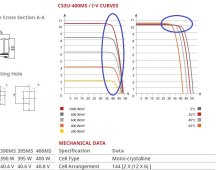
*Of course, as on the picture below, a series of 9 panels (400w) will never have a voltage of 180V when connect to the MPPT with a load. The voltage swing will be around 270V-450V depending of sun, temperature, etc.
400w panel voltage.JPG
 
That graph is with zero shading so doesn’t factor in bypass diodes. There are usually 3 bypass diodes and when active they would (roughly) drop voltage by 33%, 66%, and 100%. If a sub string is otherwise blocked then the MPPT would surely pick a voltage where there are enough bypass diodes active so current is above zero.

There’s been a lot of other advice not to do this when there are no specs summarizing this behavior of your inverter. I think if you fuse to protect the wire and what you think the limit of the inverter will be it will be safe but has the potential of blowing the fuse.

Specs and code also protect you from what you don’t know. As I said I think you overlooked a few things in your testing and analysis.
 
Moreover even without activating bypass diodes, the MPPT might still occasionally move out of the region you circled. It can be anywhere starting from 0V (yes, super unlikely, probably Vmin or Vstart would be more likely). And thinking about this more it is possible for a short duration spike in current to trip some OCPD. If they have a fast acting component, like a electromagnetic breaker. I was previously only thinking of slow thermal designs.

Since I am able to find specific areas of concerns, I don’t feel comfortable at all that I’ve enumerated all possible areas of concerns. Since a lot of people experienced in the engineering and operations of these things have concerns, that also significantly pushes me away from wanting to overpanel to this extent.

Upthread there are also a few good explanations of other reasons why using empirical measurements have limitations when going off spec.
 
See this item on over paneling:
So, without clear answer to my questioning, I read another time this item from FilterGuy and my conclusion is I can overpaneling my 3 kW inverter (at 150 kW if I want), but it's not the case of all inverter.
 
That assumes you can conclude PV Isc rating based on your testing with a battery, which I don't think is sufficient. My idea of sufficient testing would be something like knowing the schematic, and overriding the MPPT algorithm to force a low array voltage or connecting a battery to force this physically.

What is the published Isc rating?

I think the battery can be operated reasonably (unlikely to explode, unlikely to trip the OCPD) with appropriate OCPD based on output power, since the voltage will not fluctuate.
 
What is the published Isc rating?
Of my PV array? 10A, but I'm not sure it's what you want to know.
Of my EV 360V battery? Over 5000A, but I guess is not what you want to know.
Of my 3 kW inverter? There is no Short Circuit Current rating, but a 3000W rating. The only spec is 240Vdc PV nominal voltage (range 90-450V), so 12.5A at 3 kW
 
So, without clear answer to my questioning, I read another time this item from FilterGuy and my conclusion is I can overpaneling my 3 kW inverter (at 150 kW if I want), but it's not the case of all inverter.
You can do whatever you want. Whether or not it's a good idea depends on your objective.
 
Of my PV array? 10A, but I'm not sure it's what you want to know.
Of my EV 360V battery? Over 5000A, but I guess is not what you want to know.
Of my 3 kW inverter? There is no Short Circuit Current rating, but a 3000W rating. The only spec is 240Vdc PV nominal voltage (range 90-450V), so 12.5A at 3 kW
The array you propose to do has Isc well over 10A

Yes, my point is that there is no Isc on your inverter and no operating current even, just a wattage. That’s a big unprofessional red flag on the part of the vendor.

Doesn’t the PDF from FilterGuy say to use inverter Isc or max PV wattage spec which you don’t have? First bullet in Notes, Warnings and Limitations.

You seem a bit locked onto your worst case analysis and experiment setup.
 
If you're OK with arbitrary overpaneling, you're also kind of saying that you are OK with connecting an appliance into an arbitrary sized branch circuit. The analogy is:

inverter == appliance
PV array == branch circuit

EG let's take specific example of plugging in appliance with 5-15P, no nameplate, into a 50A circuit. NEC says either use nameplate max OCPD OR if not listed, do 150% of the appliance's current draw. So this combination would be disallowed unless you use a fused adapter to drop the fusing down to 25A (15A * 1.5 rounded up to NEMA standard OCPD size)
 
You can do whatever you want.
Yes, I like to do what I want. Inside the limit of the what is socially acceptable/legal and with knowledge. There is exactly the point of this thread and of my questioning: there often have a fuzzy around overpaneling some inverters, so it's why I ask for knowledge.
 
The array you propose to do has Isc well over 10A
Ah! this one. So 400A for 40 parallel strings under big sun.

Yes, my point is that there is no Isc on your inverter and no operating current even, just a wattage. That’s a big unprofessional red flag on the part of the vendor.
It's a 250$ chinese inverter. A MPP clone, so of course I don't expect miracle on the professional side.
But when I will want to buy an high quality inverter I will want to fully understand if this inverter will be able to take EV battery as solar input.
Because it's simply so nice to have a huge battery on wheels to energize the house if need.
 
Last edited:
Ah! this one. So 400A for 40 parallel strings under big sun.
Yes, big sun. And there's ways of covering/shadow the panels to still allow 3000W production but with considerably higher current. When you cover panels, cells go into blocking mode. For mono cut panels with 3 bypass diodes this means voltage will disappear at 1/3 chunks. When you have 400A Isc, the PV are no longer inherently preventing the inverter from pulling high current at lower voltage, you need the inverter to be designed properly to handle it. And this is captured in either the Isc or max DC wattage on the spec sheet.

EDIT: The way to think about why the voltage changes in that case is, basically 1/3 of the cells will get deleted at a time (assuming mono cut). The voltage is determined by how many cells you have in series, as well as the device characteristics of each individual cell.

But when I will want to buy an high quality inverter I will want to fully understand if this inverter will be able to take EV battery as solar input.

There's a good chance vendor will reject your warranty claim if you blow one up. Might be better to DC couple via an SCC so that you blow up only part of the system at once...

I was just skimming through some Victron SCC documentation, and they explicitly say, don't use it as a DC charger from a battery, because there are some edge cases that will damage the SCC. They didn't go into it (maybe someone on a forum has posted about why).
 
Last edited:
I don't know about the law where you are but here the law on installing solar PV requires you to remain within the manufacturer's specifications.
Yeah, same here for sure. Sad there is absolutely no manufacturer's specifications who allowing EV to power an house because there is no such product available right now (some companies start to show prototypes or sale product in limited quantity/place).
It's always strange to be too early on his time and look at the statu quo in place and waiting for change.
Some time I feel like a guy few decade ago who is trying to warn peoples to stop to smoke at the hospital and public places. Now it's fully ban and barely socially acceptable to smoke at all.

On the socially acceptable side, I bet my neighbor's likes considerably the fact that energize my house during an outage don't imply a lot of noise and toxic exhaust fumes.
 
Last edited:
When you cover panels, cells go into blocking mode. For mono cut panels with 3 bypass diodes this means voltage will disappear at 1/3 chunks. When you have 400A Isc, the PV are no longer inherently preventing the inverter from pulling high current at lower voltage, you need the inverter to be designed properly to handle it. And this is captured in either the Isc or max DC wattage on the spec sheet.
Ok, I start to see the potential problem. It seem to me that it's doable to do a test and connect my inverter to a 96V battery and see if it try to suck 30A to reach 3 kW or if it will simply stop sucking amps around 12.5A.
I only have 1.5kW array (4 panels) to do a test, so even if I connect panels in parallel that will only give less than 20A at around 80V (inverter take 90-450V).
 
I am guessing the savior here is the more less constant battery voltage, thus pinning the MPPT to a narrow current window:

Solar-Cell-IV-curve-with-MPP.png
 
thus pinning the MPPT to a narrow current window
What do you mean by that? For the battery connected to inverter case it would likely push the MPPT to operate in a narrow voltage band, and it would probably just draw the manageable current needed for its output rating. Though the SCC manufacturers probably won’t recommend it still.

For PV case, if you have several in series there is still a wide voltage operating range over which the MPPT can operate and buck the voltage down to the charging voltage.
 
And this is where I continually learn. Voltage is critical to an electric circuit, the amps is load driven, thus a device can only pull as many amps as it's load is designed. A short to ground (fault) is a design meant to handle ALL amps it could be fed, and is very good at consuming it.

The inverter is a special beast, that I recognize. Its goal is to reach its max output power (Volts/Amps) in watts. It juggles volts and amps to reach that point.

The bigger question is something we all acknowledge but don't like to admit that there are inverters in the market that don't do what they should. They are not to what we constitute quality design even from well known manufacturers. That's the rub, that's the hesitation.

There are some inverters that say 360v@15amps=5100watts output. However, won't they don't tell you is if you place a load on the inverter of 10,000 watts, the inverter will either try to grab more volts or amps well above the input limit to try to meet the load and go poof. These are fixed inverters, no smarts, no limits. So if you provide 100amps to the input, the inverter will grab all 100amps,*volts and try to output the watts *IF* there is a load demanding it.

My batteries come in next week, the rest of my circuit arrives this weekend. I reached out to Huawei but given the current political landscape, I doubt I'll get a reply. I'll have a quick disconnect in my circuit, a 20amp fuse inline to the inverter along with measuring devices at each critical part of my circuit. I'll hook it up, throw the lever, and see how things go boom.
Translated into a plumbing analogy. (how my Electrical Engineering prof explained it)

Volts are pressure, Amps are volume.

Too much pressure on a valve or pipe, and they will fail. (burst)
You can have all the volume you want, but without pressure, the water won't move. (like a lake)

You can have high pressure and low volume and do work. (like a power washer)
Or, have high volume at lower pressure and do the same work (buckets of water)
(an explanation of P = IV)

The same pressure is behind all the taps in your house, and as long as that pressure doesn't exceed the ratings of the pipes/fittings/valves, you won't have any leaks.
Likewise, you can open a faucet a little bit to wet your toothbrush, or lot to fill a bathtub.
You are limited by the maximum flow rate from the water source. (pressure x volume)
If you pull too much volume, pressure will drop.

Back to electrical,
You have a certain voltage (pressure) on a circuit. If that voltage doesn't exceed the ratings of the components of that circuit, it wont 'Leak' across things that it shouldn't, causing magic smoke.
Likewise the circuit will only pull the amount of watts it requires to do its job. Whether its a 15w phone charger or a 1500w hairdryer.
Or a 3000w MPPT SCC.

As long as the Voc doesn't exceed the max input voltage of the equipment, the panels can't push the power into the SCC or AIO, anymore than your ability to control the tap to brush your teeth is determined by whether you have a 1/2 inch watermain or a 3inch.
Overpanelling is fine, as long as the Voc is within limit.
 
Back
Top