diy solar

diy solar

Exceeding voltage or amps on SCC

Wouldn’t the fuse (appropriately sized) keep the string either below the specced limits, or blow if the SCC doesn’t self limit as expected? If the latter happens then you have to get a different SCC or reconfigure the panels.

The problem here seems less of a safety issue and more of poor design and planning.
 
Frankly I don't see the point.

If you need a system to generate a certain power / energy output, then install the right equipment for the job.
 
Frankly I don't see the point.
I’m actually trying to understand the best practice and what to look for in the specs.

(In practice if the specs aren’t clear enough to me, I move on and shop for something else. There’s plenty of options, I don’t need to for science this kind of thing)

Are you saying, if no specs pertaining to overpaneling (EG max input DC wattage or Isc) are provided:
1) do not overpanel
2) overpanel by a generally understood to work percentage, like 20%
2b) same as 2), but with added OCPD
 
voltage for the SCC
And this is where I continually learn. Voltage is critical to an electric circuit, the amps is load driven, thus a device can only pull as many amps as it's load is designed. A short to ground (fault) is a design meant to handle ALL amps it could be fed, and is very good at consuming it.

The inverter is a special beast, that I recognize. Its goal is to reach its max output power (Volts/Amps) in watts. It juggles volts and amps to reach that point.

The bigger question is something we all acknowledge but don't like to admit that there are inverters in the market that don't do what they should. They are not to what we constitute quality design even from well known manufacturers. That's the rub, that's the hesitation.

There are some inverters that say 360v@15amps=5100watts output. However, won't they don't tell you is if you place a load on the inverter of 10,000 watts, the inverter will either try to grab more volts or amps well above the input limit to try to meet the load and go poof. These are fixed inverters, no smarts, no limits. So if you provide 100amps to the input, the inverter will grab all 100amps,*volts and try to output the watts *IF* there is a load demanding it.

My batteries come in next week, the rest of my circuit arrives this weekend. I reached out to Huawei but given the current political landscape, I doubt I'll get a reply. I'll have a quick disconnect in my circuit, a 20amp fuse inline to the inverter along with measuring devices at each critical part of my circuit. I'll hook it up, throw the lever, and see how things go boom.
 
There’s a few extra complexity here for solar:

- depending on orientation of your panels, you could constrain the amps based on some meteorological assumptions. And decide to exceed manufacturer specs based on that’s However cloud lensing, day with specific overcast patterns, could mess up your modeling

- what’s to say your MPPT never does something dumb? Theoretically for the same output amps it could lock onto any number of input voltages while still keeping the circuit balanced. You might assume it locks onto Vmpp, but it could also pick minimum voltage, which means it will draw a lot more current to satisfy the same output
 
Is there a downside to overpaneling at the maximum safe series voltage for the SCC, and then fusing the input to the SCC at either Isc or 1.25* max current?
My personal experiment about max current: I ''overpanel'' at more than 30 time the rated current of my inverter and nothing wrong happened.
Explanations, my inverter is rated 3 kW at 240Vdc nominal (90V-450V), so 12.5A. When I connect my EV battery (360Vdc nominal able to deliver over 400A) to the solar input of my inverter, this one only take 3 kW.

My conclusion is I can overpanel a lot with my cheap PowMr inverter (MPP clone) without problem, but I don't know if all inverters will act like this.
 
Last edited:
There’s a few extra complexity here for solar:

- depending on orientation of your panels, you could constrain the amps based on some meteorological assumptions. And decide to exceed manufacturer specs based on that’s However cloud lensing, day with specific overcast patterns, could mess up your modeling

- what’s to say your MPPT never does something dumb? Theoretically for the same output amps it could lock onto any number of input voltages while still keeping the circuit balanced. You might assume it locks onto Vmpp, but it could also pick minimum voltage, which means it will draw a lot more current to satisfy the same output
The input current of the MPPT is limited not draw more than the designed.
IE input Voltage is 20V and max input Amp is capped to 10A = 20V x 10A = 200W, then it is down converted to 12V at 16.67A, now if the Voltage at the MPPT input goes up to 40V which means 40V x 10A = 400W which will equal to 33.33A, as you can see the input current is limited to 10A.
If the input Voltage is low it will allow to draw 10A max which means the charger output will be less so the charger cannot charge the battery at the rated output, it cannot maintain the same output, power in = power out (conversion loss is not factored in for simplification).
 
I agree I would use the amps rating on the PV input to estimate minimum production in various situations.

However, I am not sure one can rely on that as a safety-critical spec.

And I posted my message because it seemed like some people were appealing to the output current limit (for which there are surely several protection measures). But that needs to be combined with safety measures in the MPPT. Which would not be needed if the inverter manufacturer assumed that the current would be inherently limited by the PV array.
 
360v battery to the solar input of my inverter, this one only take 3 kW
The battery is a voltage source, which the MPPT will react differently to than a PV string. Higher voltage is also probably more well behaved for this discussion.

Will the inverter limit itself with a 100VDC battery to something sane?
 
The problem is a lot of manufacturers particularly the cheaper ones fail to provide detailed specs that directly impact the operation of the system and this should give you an indication of the quality. It should not be responsibility of end-user to guess. Missing the information you'd either need to contact the manufacturer to get a straight answer directly from them, don't go past the limits mentioned, experiment and "hope" it works, or find something else.
 
Undocumented specs is also a very risky area to be in. There could be changes in the device from year to year (parts shortages) with no indication to somebody who built a system one way would not fail with the same setup with a future version of the same device.
 
I agree I would use the amps rating on the PV input to estimate minimum production in various situations.

However, I am not sure one can rely on that as a safety-critical spec.

And I posted my message because it seemed like some people were appealing to the output current limit (for which there are surely several protection measures). But that needs to be combined with safety measures in the MPPT. Which would not be needed if the inverter manufacturer assumed that the current would be inherently limited by the PV array.
That current limit spec is not the safety spec, the circuit is designed not to draw more than what it is set to, if the circuit failed then it can draw more current,
For example, my Bluetti has max input current limited to 8A, this is made so when you using cig outlet it will not overload and blow the cig outlet fuse, now if that input current limiter circuit failed then it it can draw more Amp which will blow the cig outlet fuse, or the input fuse of the Bluetti will blow.
 
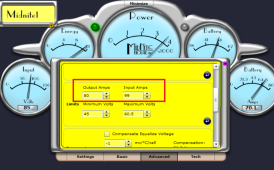
The Midnite Classic(s) have 'max amps' settings on both in and out. In particular I've limited the output to 80a because that's the size of breaker I have at the battery bus for charging. This in combination with the battery voltage will limit how much the Midnite draws from the PV array. As such, I'm over paneled a bit but not worried.

Most charge controllers don't have this feature of setting max amps.
1677705889839.png

My point is that not all charge controllers are the same and agree with comment to try to get *detailed* specs / ask the manufacturer so one can make good decisions / understand what it might mean on those exceptionally sunny/cool/cloud-reflecting moments when PV array (potential) power can spike!
 
Last edited:
Why??? DC power is DC power right?
The Voltage-Current curve on a PV panel is VERY different from a battery.

LFP battery will have not that much voltage sag up to pretty high current, possibly past the point it lights itself or the wires on fire (hopefully the BMS trips before then).

PV equivalent circuit has at its core a current source. The equivalent circuit varies in parameters based on insolation. It's not going to exceed Isc under STC, and US code wants you to 1.25 Isc to handle environments that result in more current output than STC.
 
Yes, that is what I would do, but it seems like that’s not universally accepted as the answer here.
That may well be the case but this is the wrong part of the forum for that. Such discussions should be in either:

or
 
The Voltage-Current curve on a PV panel is VERY different from a battery.
Ok, it's easy to understand the Short Circuit Current of a battery is different from PV.
But for the sake of my understanding (and for sure others) can you explain the difference between:

-150 kW capable EV battery (360V 400A)
And
-150 kW capable PV strings (40 parallel strings of 9 panels in series (400W), 360V and 400A at Imp)

All this connect to, let say, my cheap 3 kW AIO inverter.
I'm particularly interest to understand the difference because when I read your comments, it seem that you underlying that overpaneling would destroy my inverter while my EV battery work just fine with my inverter.
So, can I safely install 8000ft² of panel on my roof? ?
 
Back
Top