diy solar

diy solar

DIY Inrush Current Limiter solution needed

the amps showed 0 when inverter was off
So why not leave the inverter DC switch on all the time? If you’re not using the inverter, you can turn it off, using its power switch, and then your dad doesn’t have to do this complicated dance to have AC power when he wants it, he just turns the inverter on.
 
So why not leave the inverter DC switch on all the time? If you’re not using the inverter, you can turn it off, using its power switch, and then your dad doesn’t have to do this complicated dance to have AC power when he wants it, he just turns the inverter on.
Good question there...
Well I will have other components connected to the battery: A few USB ports (although with thier own power button) and a solar charge controller. The SCC will probably draw some current (very little, maybe a few mA when idle).

Also, I suppose that the zero power draw I saw on the PSU is because capacitors were fully charged, but capacitors do bleed off thier voltage after a while (AFAIK). So I guess that if I waited long enough, the capacitors would probably draw some more power (correct me if I'm wrong).

I want the main DC breaker to act as a safety switch too. So that when the portable generator is not in use or is being transported, basically the battery will be disconnected.

With my plans for pre-charge automation, my Dad won't have to do anything fancy. Just power up the DC breaker and in turn power up the inverter, or use DC loads (USB ports).

Maybe I'm over-complicating things, but I don't feel comfortable having the battery "always ON".
I guess maybe I'm trying to mimic consumer solar generators (Ecoflow, Bluetti, etc...) where they have a main 'ON' switch, and then you can choose to power either AC or DC loads (or both), each with its own switch (be it physical or digital on-screen).
 
I built a little test fixture to demonstrate a potential way to do the pre-charge using a solar panel.

 
One thing that has always bugged me is that if the BMS kicks off for a while, the Capacitors will discharge and when the BMS kicks back on, there will be no pre-charge..... this is one of the reasons I would like to find a clean way to automate this.
The REC precharge module in combination with a contactor is what i use for automatic operation. It is a significant added expense for a FET based BMS though.
 
My idea for automation is this (sorry no diagram yet):
Time delay relay, with NC port connected to resistor, going to inverter positive. COM port connected to 24v from battery breaker positive.
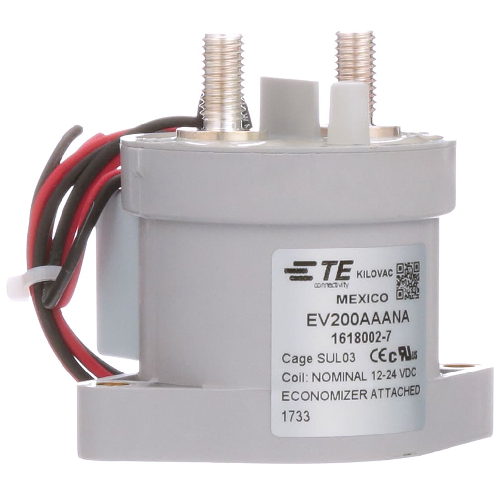
NO port connected to 125A rated DC contactor coil (that connects from breaker positive to inverter).

The time delay relay will wait for around 5 seconds since powered, and only then turn relay ON, in effect closing the DC contactor.
Meanwhile, during those 5 seconds of "OFF" time, the inverter will pre-charge.

Components that I am looking at to accomplish this:


and of course a relevant resistor.

The only issue with this specific time delay relay is, that while input voltage is up to 30v (suitable for 24v Lifepo4 battery), it's trigger signal is only up to 24v (which is basically the voltage of an almost empty 24v Lifepo4).
But, I noticed that this time delay relay also has a 5v pad on the back of the PCB (probably via an on-board voltage regulator), so I might use it to trigger the signal port when it receives power.

I hope I explained myself well. I will try to create a diagram when I get to doing so.

In my previous solar generator build (12v Lifepo4) , I also used a different time delay relay, but no contactor. As soon as I hear the relay turning off, I close another breaker going to inverter, so it's semiautomatic I guess.

But now my Dad also wants one, so I'm building a new one for him (with 24v Lifepo4) , and I want to make it fool proof. That's why I'm looking for automation.
Basically, when he needs to use the solar generator, he will just turn on the DC breaker and then after around 5 seconds, the inverter can be powered ON.
Just a small update:
While checking the specific time delay relay, I found that it doesn't do what I need/expect:
1. Mode P2 is the most suitable (OFF -> DELAY -> ON). NC port will have the pre-charge resistor, NO port will power up the contactor.
The problem with this mode is that if a constant signal/trigger is applied, it resets.
2. The ON time is limited to 999 minutes. I would like it to be infinite.

I have a 12v version of a more simple time delay relay that work as expected in my 12v system (semiautomatic pre-charge), but I'm have a hard time finding a 24v equivalent.
I'm considering just using the 12v module with a step down converter.

Also, I found that it's not so simple to power a DC contactor: You need to take into consideration coil back EMF and optimize the coil power (coil economizer), or else you risk excessive heat buildup of the coil and power waste.
I recently received a 24v 125A DC contactor, but when powered up, it takes almost 500mA of power to keep the contactor closed.

I ended up order a Tyco with built in economizer, but have to wait for delivery a day wasted money with the simple DC contactor.
 
Have you spent $280 on this project yet? I tried everything I knew to automate my startup without tripping my SOK BMS's and failed miserably. Finally broke down and got the BattleBorn CSL500 and all is good. It just works.
 
Have you spent $280 on this project yet? I tried everything I knew to automate my startup without tripping my SOK BMS's and failed miserably. Finally broke down and got the BattleBorn CSL500 and all is good. It just works.
Wow, that's alot of money for some fets, a resistor and a timer...
 
Have you spent $280 on this project yet? I tried everything I knew to automate my startup without tripping my SOK BMS's and failed miserably. Finally broke down and got the BattleBorn CSL500 and all is good. It just works.
I still like my DIY version.
 
OK, so after hunting around Aliexpress, I think I found what I'm looking for:


It's a time delay relay available in 5,12 and 24v.
What's special about this one, is that has more programs than the previous one I quoted. Specifically I think program P-22 will do the job (if you hardwire input to signal ports):
SmartSelect_20240313-072910_Chrome.jpg
This will delay the ON of the relay, but when signal is dropped (DC breaker will be turned off) it will reset.

I also like the fact that they have an enclosed model, in a nice little case.

While searching Aliexpress, I also stumbled upon two interesting items:
1.
This is an AC inrush current limiter. Not applicable to our needs because it's AC only, but it was interesting to see that these exist and are fairly cheap. Too bad they don't have a DC version.

2.
This little device is relevant for powering the DC contactor. It's basically a small inrush current limiter, but limited to 1000w, so not relevant to be used with a powerful inverter. But, it can ease up on the time delay relay's contacts, when powering up the DC contactor coil. I don't know if it's really necessary, but since this item is so cheap, I figured I would get some and use for extending the lifespan of the relay contacts.

BTW, I plan on implementing low-voltage power down for the inverter, since it's low voltage threshold is too low: 20v.
I plan on doing this by tapping into the remote display switch, and pass it onto a voltage sensing relay that will cut-off @ 24v.
But that's for another thread.

So now all I need to do is... wait for the darn items to arrive from China...
 
OK, so after hunting around Aliexpress, I think I found what I'm looking for:
... clip

While searching Aliexpress, I also stumbled upon two interesting items:
1.
This is an AC inrush current limiter. Not applicable to our needs because it's AC only, but it was interesting to see that these exist and are fairly cheap. Too bad they don't have a DC version.
... clip
This is interesting, maybe I can use this as a cheaper soft-start for HVAC compressor. I ordered both voltages, the 110V probably can be modified to work on DC. There are four 20 ohms NTCs probably for the delay, I assume they are connected in parallel.
 
This is interesting, maybe I can use this as a cheaper soft-start for HVAC compressor. I ordered both voltages, the 110V probably can be modified to work on DC. There are four 20 ohms NTCs probably for the delay, I assume they are connected in parallel.
So my order came and I tested it on an air compressor it seems to work but I did not do any measurement.
Here is a picture of the device as received.
pic1.jpg

Most components removed for circuit tracing.
pic2.jpg

Here is the circuit.
SCHEMATIC1 _ Soft Start.jpg
The relay coil measured 82 ohms and at 12V it will draw about 0.15A. I think it will work for DC if the terminals of C2 (with AC 110V sticker) is jumpered with appropriate value resistor. Assuming a 1 volt drop in the bridge diodes, needed DC input to the converter will 18 volts.

So if IN-L is +24 volts, drop in the resistor will be 24-18 = 6 volts and resistance will be 6/.15 = 40 ohms and dissipation is 0.9 watts, use 2 watts.

Note that the relay used has a chinese rating of 100A for the contacts.

Edit:
was - terminals of C4 (with AC 110V sticker)
now - terminals of C2 (with AC 110V sticker)
Thanks @wpns.
 
Last edited:
So my order came and I tested it on an air compressor it seems to work but I did not do any measurement.
Here is a picture of the device as received.
View attachment 203491

Most components removed for circuit tracing.
View attachment 203492

Here is the circuit.
View attachment 203493
The relay coil measured 82 ohms and at 12V it will draw about 0.15A. I think it will work for DC if the terminals of C4 (with AC 110V sticker) is jumpered with appropriate value resistor. Assuming a 1 volt drop in the bridge diodes, needed DC input to the converter will 18 volts.

So if IN-L is +24 volts, drop in the resistor will be 24-18 = 6 volts and resistance will be 6/.15 = 40 ohms and dissipation is 0.9 watts, use 2 watts.

Note that the relay used has a chinese rating of 100A for the contacts.
Wouldn’t you jumper C1, C2 with a resistor in order to use it at DC?
 
Wouldn’t you jumper C1, C2 with a resistor in order to use it at DC?
Yes, typo on my part sorry about that. Since C1 and C2 are in parallel, only one needs to be jumpered.
 
I wouldn't trust the relay for 100a DC, nor the terminals...

I just received my Tyco contactor and the 24v time delay relays today.
The Tyco is for 12-24v (coil voltage) and has a built in economizer (a little PCB, which reduces coil current after initial power up).
This is the one:

I would love to start testing, but am gonna be busy this weekend, so it will be delayed.
 
I started testing with the TYCO contactor and the 24v time-delay relay.
I ended up choosing program P-28 on the relay:
SmartSelect_20240331-001304_Chrome.jpg
That way as soon as it's powered up, it will wait the delay and then power up my contactor.

I still haven't setup the power resistor for pre-charging, but this will be connected to the NC port of the relay. On the COM port I will have 24v positive and on the NO port I have the contactor positive.

I also installed the RC Snubber, not sure it's really needed, but it's suppose to suppress any voltage spike induced when the coil of the contactor is de-energized.
I hot glued it onto the relay casing, just for ease of use.
20240330_232420.jpg20240330_232432.jpg20240330_232441.jpg

It works nicely!
 
One thing that has always bugged me is that if the BMS kicks off for a while, the Capacitors will discharge and when the BMS kicks back on, there will be no pre-charge..... this is one of the reasons I would like to find a clean way to automate this.
@FilterGuy did you ever find a resolution that takes into account this issue?
 
I came up with this circuit to automate bypass contactor closure. It's a comparator that turns on once the difference between battery voltage and load side voltage drops to within 1V. Need to add latch circuit to prevent possible contactor chatter or oscillation.

20240420_151132_resized2.jpg
 
@FilterGuy did you ever find a resolution that takes into account this issue?
My solution using the time-delay relay solves this too.
Basically, whenever BMS discharge is enabled, and main DC breaker is ON, there is a path to the inverter via resistor, and after 5-10 seconds the time delay relay switches the contactor ON.
If the BMS cuts out, or the main DC breaker is turned OFF, the whole cycle repeats on next power up (5 seconds pre-charge, then power up of the contactor).
 
Back
Top