pretzelboy
New Member
Hello All,
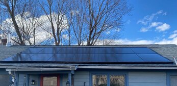
Yesterday I replaced 20 old Sunpower 210 watt panels from 2010 on a house roof array.
The system was professionally installed and has been trouble free.
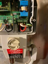
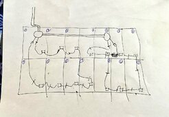
Once the new array was installed (14 Canadian Solar CS6R- 390MS-HL panels) two strings of 7 panels each. Everything connected, checked and panel and rack grounding secured.
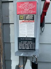
it was dark when finished so just checking this morning - I have no error codes but a flashing green light on the SPR 4000m inverter
the system reads
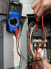
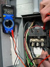
Pac 0W and VPV 256V
Gridtype 240V
L1 120V L2 119V
indicates "waiting"
I have rebooted inverter twice shutting inverter off, then PV disconnect, waiting a minute then inverter then ac reconnect. Inverter seems to boot up fine but right back to situation above.
Any advice on what to work back or forward from to rectify this situation? I read a lot about how the inverter could fail but it doesn't seem to be that from what im experiencing
Thanks G
Yesterday I replaced 20 old Sunpower 210 watt panels from 2010 on a house roof array.
The system was professionally installed and has been trouble free.
Once the new array was installed (14 Canadian Solar CS6R- 390MS-HL panels) two strings of 7 panels each. Everything connected, checked and panel and rack grounding secured.
it was dark when finished so just checking this morning - I have no error codes but a flashing green light on the SPR 4000m inverter
the system reads
Pac 0W and VPV 256V
Gridtype 240V
L1 120V L2 119V
indicates "waiting"
I have rebooted inverter twice shutting inverter off, then PV disconnect, waiting a minute then inverter then ac reconnect. Inverter seems to boot up fine but right back to situation above.
Any advice on what to work back or forward from to rectify this situation? I read a lot about how the inverter could fail but it doesn't seem to be that from what im experiencing
Thanks G
")