diy solar

diy solar

JK-BMS-CAN with new Cut-Off Charging Logic (open-source)

Hi @paulsteigel, the existing auto charge current control does similar to this already.
At the moment, we're working on controlling charge current through dynamically adjusting the requested CVL. That's the more effective way to do it, assuming your inverter regulates CVL properly...
My Inverter prefer fix charge voltage. I observed some dedicated BMS shipped with whole pack of high quality battery over months connected to the inverter via Rs485 and it only applies a single voltage 56V during the charging and sometime does resetting SOC by trying to lengthen the charging process to make cell be as close to 3.45 as better. Over a year, I could hardly see the min cell voltage drop below 3.1V and few time discovered the max voltage reach 3.46.
The only things I found was changing of charging current limit.
The reason I moved to map function was the "High voltage warning" by the inverter. For the case of 280Ah battery pack, charging current reached 70-80A and make the cells become so unbalanced and current dropped a bit too quickly and make cells became less unbalanced. As the result the current get back high again.
I tested today with map(), current changed a bit slower comparing to yours great function (both in increasing and decreasing as well). My trick was defining a buffer such as 50mV toward the OVP (defined by user, not by the BMS and often 3450mV) and 10mV above the OVP. So when max_cell_volt increased as closer to the OVP the current will be mapped down from the initial charging current defined by user often 0.25 - 0.3C.
I used old code of Sleeper85 and revised quite remarkably to meet with Luxpower SNA5000. If tomorrow test is successful I will share back!
I learned from you alot by using the platform: copy. Before I have to rely on script.
In general, my approach is to help Inverter treating battery pack as lead acid.
I have small problem occurred today that Inverter complained "Battery High voltage" with one of my friend (SNA5000 but it does not happen with a SNA6000 of the same yaml code) when he charge with 50A current so he turn back to Lead acid and charge went well again using 57.5V without problem. So I doubt there would be problem relating to the reporting of charging voltage from BMS (CAN_ID 0x356) or (CAN_ID 0x351). I discussed with Luxpower Dealer on this point but he failed to explain (he might not know about this).

This is today record of the premium BMS with SVE5000WM battery
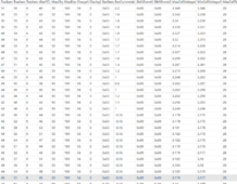
1711984676338.png

And this is today charging using map() for 50Ah battery
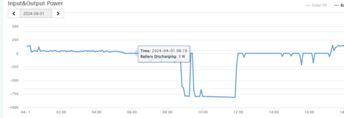
1711984774887.png
And this is today charge using your power() option with manual control of charging current
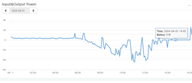
1711984870928.png
 
Last edited:
So I doubt there would be problem relating to the reporting of charging voltage from BMS (CAN_ID 0x356) or (CAN_ID 0x351). I discussed with Luxpower Dealer on this point but he failed to explain (he might not know about this).
Now that you have mentioned, I too have a Luxpower SNA 5000 and everything is working for me at my end for months. Let me know what settings are you using and what version specifically.
 
Also, if it bears mentioning again and again. When there is current going in/out of the battery, its balance can't be determined due to internal resistance.
Very Ideally, determining battery balance involves removing all external potentials across the battery (such as can be achieved by turning BMS Charge MOS off) and letting the cells rest for like half an hour or so.
Then the voltage measured of the cells will correspond to the true balance voltages. Theoretically, this is also the ideal time for a balancer to do its job. after a full charge with no current going in/out, and no external potential to affect voltage readings.

Everything else is a compromise, loosely speaking.
 
Now that you have mentioned, I too have a Luxpower SNA 5000 and everything is working for me at my end for months. Let me know what settings are you using and what version specifically.
Yap, it was very strange as the code worked (the Mr.Pablo one) on the SNA6K version, but the same code failed on the SNA5000. I tried a few options but it was too late, no more solar today. Will try tomorrow on 0x356 and 0x351 to report lower voltage for checking what has happened!
 
Also, if it bears mentioning again and again. When there is current going in/out of the battery, its balance can't be determined due to internal resistance.
Very Ideally, determining battery balance involves removing all external potentials across the battery (such as can be achieved by turning BMS Charge MOS off) and letting the cells rest for like half an hour or so.
Then the voltage measured of the cells will correspond to the true balance voltages. Theoretically, this is also the ideal time for a balancer to do its job. after a full charge with no current going in/out, and no external potential to affect voltage readings.

Everything else is a compromise, loosely speaking.
You are totally right! That is why we are here with Pablo and other working hard to find a solution for this! What we are doing is making the JK work better as we can expect it to function perfectly! I myself believe current limit and voltage limit are two feasible options then!
 
Yap, it was very strange as the code worked (the Mr.Pablo one) on the SNA6K version, but the same code failed on the SNA5000. I tried a few options but it was too late, no more solar today. Will try tomorrow on 0x356 and 0x351 to report lower voltage for checking what has happened!
your battery brand setting?

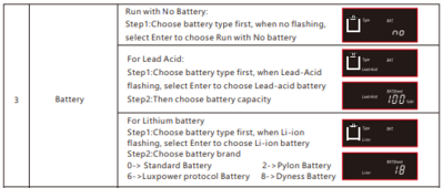
setting PYLON + and Battery brand 2 is recommended for LXP SNA.5k
Additionally try cleaning up the project files and doing a fresh recompile.
 
your battery brand setting?
on JK OVP is 3.55V, current limit for charge 100A, discharge 100A but I have addition layer of limits on esphome with max_cell_protection of 3450mV and Charge current limit of 70A. On SNA, Charge limit is 100A but it listened to the BMS via CAN, Voltage was 57.4 (default set for lead acid and still kept as it is). Lux stop charging at some period and reported W025 - Battery High voltage). He changed to lead acid and charge went well without problem. Haiza - this is headache. This did not happen with another guy usign SNA6K. He even push the current to almost 80A
1711985658371.png
 
Not on JK, I'm asking specifically what CAN protocol you are using in YAML script dashboard
AND
What battery brand under lithium battery you are using in your LXP SNA 5k?
inverter set .png
 
on JK OVP is 3.55V, current limit for charge 100A, discharge 100A but I have addition layer of limits on esphome with max_cell_protection of 3450mV and Charge current limit of 70A. On SNA, Charge limit is 100A but it listened to the BMS via CAN, Voltage was 57.4 (default set for lead acid and still kept as it is). Lux stop charging at some period and reported W025 - Battery High voltage). He changed to lead acid and charge went well without problem. Haiza - this is headache. This did not happen with another guy usign SNA6K. He even push the current to almost 80A
View attachment 206255
57.4v is a high charge voltage assuming a 16s battery. General guidance is to bulk charge at 3.45v per cell, so 55.2v.
This will give sufficient headroom for balancing without triggering OVP, etc, but also fully charge the battery.
 
57.4v is a high charge voltage assuming a 16s battery. General guidance is to bulk charge at 3.45v per cell, so 55.2v.
This will give sufficient headroom for balancing without triggering OVP, etc, but also fully charge the battery.
Hi Mr. Pablo,
The following is captured data from the inverter (the 6K)
1712022746546.png
It seemed charging voltage does not update by the the BMS but regulated by the inverter.1712022814553.png
So I can concluded that via CAN bus Luxpower Inverter will not change its charging voltage as requested by the BMS via Pylon protocol. The following image is the one with BMS communicating to the Luxpower via RS485 and charging voltage is changed by BMS request.
I set the charging voltage of 57

1712023047354.png
But the BMS (via Rs485) requested 56 and it charges with 56V
1712023094421.png
That's interesting!
 
Today, I did a final check with inverter dealer (technical guy) and discovered that the voltage sensor (type of voltage divider resistor) on the inverter was not in good condition and cause the reading voltage from battery wrong (Vbat_inv) and often high when charging. as the result the High voltage alarm trigger by the inverter and stop charging.
The charging with revised config worked out well on 104Ah battery and 280ah battery and also 50Ah.
104Ah battery with auto charge current using map(): 4.4kWh was charged
1712039541901.png
And here is the one with 280Ah battery, 13.3kWh charged (using manual charging current control) - the guy does not want to control automatically. He wants to rip the more solar the better. haiza
1712039772099.png
And this is for my case auto charging with 50Ah battery. 2.7 kWh was charged.
1712039855537.png
Please be sorry Mr. Pablo for revising the code too much (I based on the 2 months ago code provided by Sleeper85)
Here is the link for the revised one / messy but sound fun.
With this cutting on code, the bms battery can work almost the same as a lead acid battery but Inverter can check view stuff on battery
I am planning to do more with
+ Control charging current by time: still wonder how to have time entity in home assistant be used in esphome code.
+ Find a way to deal with charge voltage limit control (still not possible to do in Luxpower inverters)
+ There is also problem on calculating charging cycle that Lux does not accept. So I will try finding a way to work this out!
+ Also a bit more revision on current limit recovery should be applied to make the charging curve be smooth (should not back to high current again to avoid some power rush in);
+ Fixing end of charge stage: currently my revision make the charge prolonged, and can only be stoped when charging voltage is high (57.4 for 16S battery on Luxpower inverter).
Many thanks yo Slepper85 for your starting code and Mr.Pablo for your wonderful code on platform: copy (that save me tons of time). And please be sorry for removing a lot of your code in 0x355 and 0x351 section.
Best!
For your information: this is the charging curve for SVE5000 battery (premium) - 4.4Kw charged to day
1712041347163.png
Yesterday charge using @MrPablo pow() function and today using map(): for my 50Ah battery
1712041520974.png
 
Last edited:
Today, I did a final check with inverter dealer (technical guy) and discovered that the voltage sensor (type of voltage divider resistor) on the inverter was not in good condition and cause the reading voltage from battery wrong (Vbat_inv) and often high when charging. as the result the High voltage alarm trigger by the inverter and stop charging.
The charging with revised config worked out well on 104Ah battery and 280ah battery and also 50Ah.
104Ah battery with auto charge current using map(): 4.4kWh was charged
View attachment 206437
And here is the one with 280Ah battery, 13.3kWh charged (using manual charging current control) - the guy does not want to control automatically. He wants to rip the more solar the better. haiza
View attachment 206438
And this is for my case auto charging with 50Ah battery. 2.7 kWh was charged.
View attachment 206439
Please be sorry Mr. Pablo for revising the code too much (I based on the 2 months ago code provided by Sleeper85)
Here is the link for the revised one / messy but sound fun.
With this cutting on code, the bms battery can work almost the same as a lead acid battery but Inverter can check view stuff on battery
I am planning to do more with
+ Control charging current by time: still wonder how to have time entity in home assistant be used in esphome code.
+ Find a way to deal with charge voltage limit control (still not possible to do in Luxpower inverters)
+ There is also problem on calculating charging cycle that Lux does not accept. So I will try finding a way to work this out!
+ Also a bit more revision on current limit recovery should be applied to make the charging curve be smooth (should not back to high current again to avoid some power rush in);
+ Fixing end of charge stage: currently my revision make the charge prolonged, and can only be stoped when charging voltage is high (57.4 for 16S battery on Luxpower inverter).
Many thanks yo Slepper85 for your starting code and Mr.Pablo for your wonderful code on platform: copy (that save me tons of time). And please be sorry for removing a lot of your code in 0x355 and 0x351 section.
Best!
For your information: this is the charging curve for SVE5000 battery (premium) - 4.4Kw charged to day
View attachment 206441
Yesterday charge using @MrPablo pow() function and today using map(): for my 50Ah battery
View attachment 206442
I will test this - however, it's a shame that this revision will only be used on a personal rather than a global level as work that has been done between versions 16.5 and 17.4 has been cut out (which is a lot of work and effort).

We should be moving forward as a community in the project development and thriving to work together so no effort is in vain.
I wish you could have done your revision from the latest 17.4 version...but it is what it is, I am sure you have your technical reasons and explanations (my knowledge of coding is limited so I have no opinion except on a general ground).
Same feeling here ... Would be better to have an "all-in-one" software or at least a "all-in-one" framework going forward.

But it is what it is. I can also understand people doing their own spinoffs. Their use case is quite specific, integration is different, they might not be able to wait, etc

Plus that's the entire principle of how GitHub works. First you fork a repo, then you do the modifications. But then it's also up to you to either upstream (giving back to the community) and integrating into their newest code. It has to be a pretty big feature you developed on your own side to "justify" the main project to do a "pull" from your fork instead and them doing all the integration work IMHO.
 
Last edited:
Same feeling here ... Would be better to have an "all-in-one" software or at least a "all-in-one" framework going forward.

But it is what it is. I can also understand people doing their own spinoffs. Their use case is quite specific, integration is different, etc

Plus that's the entire principle of how GitHub works. First you fork a repo, then you do the modifications. But then it's also up to you to either upstream (giving back to the community) and integrating into their newest code. It has to be a pretty big feature you developed on your own side to "justify" the main project to do a "pull" from your fork instead and them doing all the integration work IMHO.
Thanks to @silverstone and @chaosnature!
I just tried a test first and then moving on shaping the code back to the main version that Sleeper85 and Mr. Pablo is working! The initial result shown that it can work as expected for at least Luxpower/Deye Inverters (what I have for testing and they are still having minor problems to be solved as stated earlier). From that perspective, the options that @MrPablo and @Sleeper85 provided worked and can be used for wider application. With some modifications on Charging/discharging logics to make the charge/discharging curve be more smooth, I believe it would fit the need for bringing values to make the cheap JK-BMS talk properly to Inverters.
I will do revision anyhow as I have been struggling using this pathway to make the battery be charged as a "Lead acid" pack but it can talk! The only worrying is, There are codes from both Sleeper85 and Mr.Pablo that has been changed massively comparing to the version that I am working on:
1. I did not apply the charging logic set under the 0x351: as I found out that people use different setting for charging: some charge/discharge once a day, the other applies constant charge/discharge to maximize the use of solar. Also, I don't want to rely on alarm from BMS but applying a proactive prevention method to avoide warning on the inverter (often applied by premium BMS). This is the reason why I removed almost all code under this 0x351 section. Furthermore, since JK SOC is not reliable it is impossible for detecting the charging/discharging stage.
2. I learned from Mr.Pablo approach to replace scripting so whenever max/min_cell_voltage and SOC hit a point for checking, the code will do the work so that Inverters will not stop charging or throwing a warning that worries users.
3. There is not much I created but revising Mr.Pablo's code just a bit on charging current limit and SOC check!
with this I believe the puzzle can be solved in a simpler and easier approach and can fit different needs. Anyway I will make a fork from the code repo and rewrite the code.
Best,
 
Last edited:
Thanks to @silverstone and @chaosnature!
I just tried a test first and then moving on shaping the code back to the main version that Sleeper85 and Mr. Pablo is working! The initial result shown that it can work as expected for at least Luxpower/Deye Inverters (what I have for testing and they are still having minor problems to be solved as stated earlier). From that perspective, the options that @MrPablo and @Sleeper85 provided worked and can be used for wider application. With some modifications on Charging/discharging logics to make the charge/discharging curve be more smooth, I believe it would fit the need for bringing values to make the cheap JK-BMS talk properly to Inverters.
I will do revision anyhow as I have been struggling using this pathway to make the battery be charged as a "Lead acid" pack but it can talk! The only worrying is, There are codes from both Sleeper85 and Mr.Pablo that has been changed massively comparing to the version that I am working on:
1. I did not apply the charging logic set under the 0x351: as I found out that people use different setting for charging: some charge/discharge once a day, the other applies constant charge/discharge to maximize the use of solar. Also, I don't want to rely on alarm from BMS but applying a proactive prevention method to avoide warning on the inverter (often applied by premium BMS). This is the reason why I removed almost all code under this 0x351 section. Furthermore, since JK SOC is not reliable it is impossible for detecting the charging/discharging stage.
2. I learned from Mr.Pablo approach to replace scripting so whenever max/min_cell_voltage and SOC hit a point for checking, the code will do the work so that Inverters will not stop charging or throwing a warning that worries users.
3. There is not much I created but revising Mr.Pablo's code just a bit on charging current limit and SOC check!
with this I believe the puzzle can be solved in a simpler and easier approach and can fit different needs. Anyway I will make a fork from the code repo and rewrite the code.
Best,
I am sure a compromise can be reached between yourself and MrPablo to integrate the proposed changes into the latest version; as it does make sense, the case you are putting forward....

again hard to tell with my limited coding knowledge
 
I will do revision anyhow as I have been struggling using this pathway to make the battery be charged as a "Lead acid" pack but it can talk!
LFP work differently/ have different charging behaviour from lead acid.
+ Find a way to deal with charge voltage limit control (still not possible to do in Luxpower inverters)
This works perfectly fine (even the response is within 1 or 2 seconds) on my LXP SNA 5k unit. This has to be an issue on your end.
Furthermore, since JK SOC is not reliable it is impossible for detecting the charging/discharging stage.
When it comes to LFP specifically, we have to rely on voltages to detect the charging/discharging stage and what to do.
That is how this chemistry is. SOC is bound to deviate because it is a derived and furthermore, an integrated over time quantity.

Newer JK's provides an option for setting a voltage corresponding to 100% charge.
With some modifications on Charging/discharging logics to make the charge/discharging curve be more smooth, I believe it would fit the need for bringing values to make the cheap JK-BMS talk properly to Inverters.
You can always turn the switches for AutoCVL/CCL/DCL off and have an unadulterated charging.

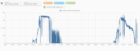
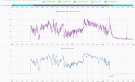
Here's mine doing the same.
The graph between cell deviation and current/power is mostly same until a spike at the very end of the bulk phase

1712067914697.png

My pack is balanced that is why I don't require anything. I can fully charge my pack with balancing mostly turned off.
From what I know the JK-BMS+ESP solution is already talking nicely with inverters that we have tested so far.
It is finally I can sleep soundly at night level good!!
 
LFP work differently/ have different charging behaviour from lead acid.
When it comes to LFP specifically, we have to rely on voltages to detect the charging/discharging stage and what to do.
That is how this chemistry is. SOC is bound to deviate because it is a derived and furthermore, an integrated over time quantity.
It was a metaphor to imply the simplicity for users when they apply this method to allow Lux to manage the charging process without worrying once correct limits on voltages are configured on the inverter. I did some changes on the code for bringing voltage control to manipulate charge/discharging behavior. This would be so much similar to the case of Lead Acid.
This is why @Mr.Pablo biding on cell_max/min is very reasonable. and I am using his approach for detecting problems to cells voltage
This works perfectly fine (even the response is within 1 or 2 seconds) on my LXP SNA 5k unit. This has to be an issue on your end.
This is true on SNA5000WM. I used pylon protocol (brand 2) but Lux does not change the charged voltage at all (I tried on all 3 SNA5000 and the 6K version, helpless)! However, I recalled that SNA5000WM did changed the charge voltage when using with SVE battery (connected via RS485) and today a guy from Lux shared that it can also change via CAN bus using protocol 1. So I believe Lux might response on other can_id. (Similarly, 0x70 does not update cell voltage (max/min) on Lux with brand 2 (pylon) but 0x373.
Newer JK's provides an option for setting a voltage corresponding to 100% charge.
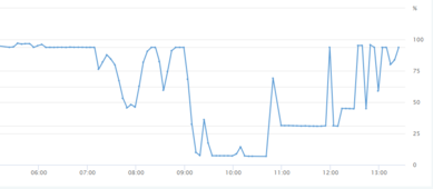
This true but JK's SOC still deviates over time and it need a method to reset at both end (0% and 100%) to allow proper work for the inverter (when using Lion mode, Inverter use SOC but not Voltage to regulate its charging/discharging process. I have tried several way to control Lux on voltage but it failed). Therefore SOC fine tuning become important.
Normally to reset that, user will do on JK mobile app but we have another option to do it by keep charging when SOC at 100% or discharging when SOC is 0% (in my case when Bat_v is still 49.5 - 15S pack and min/max cell still over 3.2V)
1712072113616.png
You can always turn the switches for AutoCVL/CCL/DCL off and have an unadulterated charging.
I reckoned the feature and did trying but the charging schemes under 0x356 cause problems to the bulk charge for high current. It's might be a case that I did not use the new version in GitHub. I will try tomorrow to see any problem with that.
Thank you for your detailed shares. All we are heading for is to reach a state that we can plug in and forget for the ESP to manage the process! I do like to end up this and back to Lead acid but the feeling of wanting to make the battery speak does not stop tracing me even in during my sleep.
Best!
 

Attachments

  • 1712072172073.png
    1712072172073.png
    5.3 KB · Views: 3
Sorry to randomly crash in here on page 44, but i cant for the life of me get this Atom S3 lite device to be recognized under the windows platform, and thus cant edit any files.

When power up the atom, all i see is a password protected WIFI network ( no clue what the password is )

Can anyone lend a hand here?
I gave up on windows so I cannot help you there 😅.

But what exactly do you mean that you cannot get the Atom S3 Lite recognized under windows ?

If you power it up without having uploaded the program (and how could you have done that if it's not even getting recognized), I guess it's just some demo program running from the manufacturer ....

Did you setup the esphome build environment correctly ? If you had Linux or could use a Linux VM (NOT WSL !) or Dual Boot it would be easier IMHO.

I might be totally off track here, but I was under the impression that my windows operating system ( where I installed esphome ) have to be able to communicate with the atom in order to edit or update files necessary for this project.

After installing esphome I got a red error message that read "ERROR resolving IP address of jk-bms-can.local. Is it connected to WIFI?"

But I have no clue what the WIFI password is ( I suppose it came installed with something because a wifi network called AtomS3.xxxxx pops up when i power it up. :unsure:
Did you flash it using the USB cable ? Did you set the domain name / hostname correctly to the YAML file and do you have a working DNS server ?

Otherwise for OTA to work, either your DNS Server must be able to resolve that FQDN (hostname + domain name), or:
- Linux: add the IP address to /etc/hosts
- Windows: add the IP address to C:\Windows\System32\drivers\etc\hosts

And of course up to you to find the IP address of the device. Look at the Lease Table of your DHCP server for that (or run a fing/nmap scan etc).

Personally OTA has proven quite unreliable to me, so I only use the USB cable to flash ...

Not been able to flash anything, when I plugin the atom to my computer using a USB to type-c cable, all I get is the atom powers up, the LED lights up in red, and will turn green / blue / white if I cycle it's button.

I tried to debug the USB port to see any information from the atom could be revealed ( looked for vendor_ID or anything in order to find potential drivers , but nothing.. ).

I visited https://docs.m5stack.com/en/download to look for windows drivers, randomly installed a few, since I dont know what chip / driver is needed for this particular Atom,, but nope, no luck.
But did you try the esphome command at all or ? It should find the adapter automatically after compiling the program, it will ask you whether you want to flash USB device or if you want OTA. If nothing is plugged in, it will just do OTA automatically.

About windows not detecting anything ... Are you sure you are using a Power+Data USB cable ? Some USB cables are meant only for power so if you miss the data pins/wires it's not going to work. Just cross-checking :) .
 
It was a metaphor to imply the simplicity for users when they apply this method to allow Lux to manage the charging process without worrying once correct limits on voltages are configured on the inverter. I did some changes on the code for bringing voltage control to manipulate charge/discharging behavior. This would be so much similar to the case of Lead Acid.
This is why @Mr.Pablo biding on cell_max/min is very reasonable. and I am using his approach for detecting problems to cells voltage

This is true on SNA5000WM. I used pylon protocol (brand 2) but Lux does not change the charged voltage at all (I tried on all 3 SNA5000 and the 6K version, helpless)! However, I recalled that SNA5000WM did changed the charge voltage when using with SVE battery (connected via RS485) and today a guy from Lux shared that it can also change via CAN bus using protocol 1. So I believe Lux might response on other can_id. (Similarly, 0x70 does not update cell voltage (max/min) on Lux with brand 2 (pylon) but 0x373.

This true but JK's SOC still deviates over time and it need a method to reset at both end (0% and 100%) to allow proper work for the inverter (when using Lion mode, Inverter use SOC but not Voltage to regulate its charging/discharging process. I have tried several way to control Lux on voltage but it failed). Therefore SOC fine tuning become important.
Normally to reset that, user will do on JK mobile app but we have another option to do it by keep charging when SOC at 100% or discharging when SOC is 0% (in my case when Bat_v is still 49.5 - 15S pack and min/max cell still over 3.2V)
View attachment 206497

I reckoned the feature and did trying but the charging schemes under 0x356 cause problems to the bulk charge for high current. It's might be a case that I did not use the new version in GitHub. I will try tomorrow to see any problem with that.
Thank you for your detailed shares. All we are heading for is to reach a state that we can plug in and forget for the ESP to manage the process! I do like to end up this and back to Lead acid but the feeling of wanting to make the battery speak does not stop tracing me even in during my sleep.
Best!
This true but JK's SOC still deviates over time and it need a method to reset at both end (0% and 100%) to allow proper work for the inverter .....

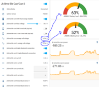
the above statement is definitly true in my case .....the both jk seem to align towards the 0% SoC but leave each other when they appraoch 100 % SoC
1712077077412.png

They do not seem to obey the voltage count.....


# Edit
According to the voltage vs percentage screenshot above...my calculations says if 3.704 is = 63 % then 3.734 should = 63.510 %
But it's reading 52%
 
Last edited:

diy solar

diy solar
Back
Top