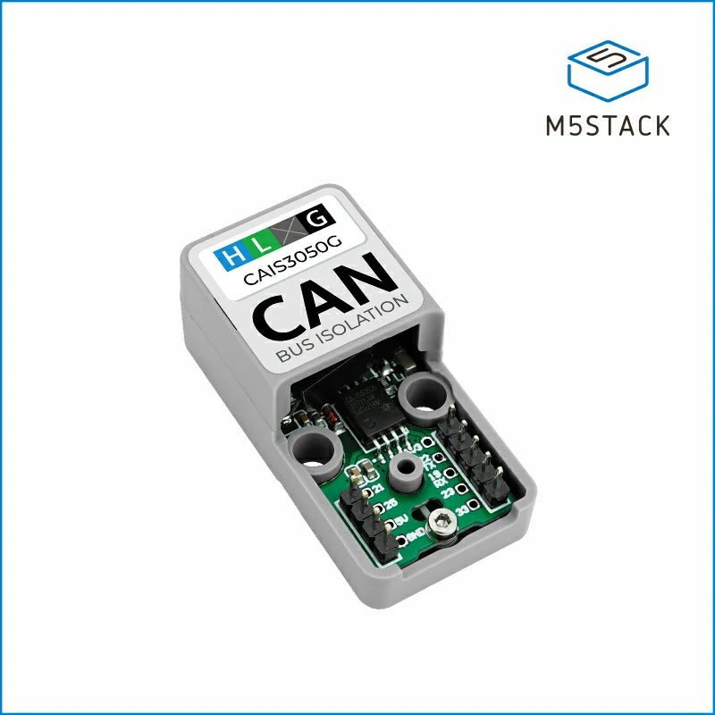
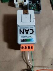
- Please CONFIRM the SKU part number of the M5Stack Controller (Atom S3 Lite) and especially the CANbus Isolated Adapter (one is UNIT the other is BASE). I was using the wrong one (UNIT/Base confusion, availability at suppliers, ...) so the GPIO pinout was wrong.
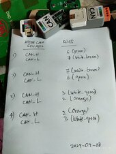
- Did you try reversing CAN_TX and CAN_RX ? Did you try reversing the GPIO pins on the ESP32 side in the config ?
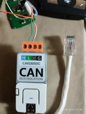
- Did you try pin 2+3 or 6+7 ? Depending on how you look at the RJ45 Plug (from front or from back ? with "locking tab" facing up or down ? etc) or RJ45 Socket (from front or from back ? with space for the "locking tab" facing up or down ? etc) it can be different. And of course there are plenty of "opportunities" to switch everything around. I was VERY methodical for the RS485 Inverter Communication (NOT the CANbus where I got the pinout wrong ...), but it's VERY easy to get it backwards ...
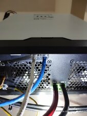
This is for my Deye Modbus Port:
View attachment 207631
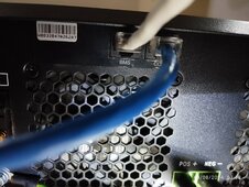
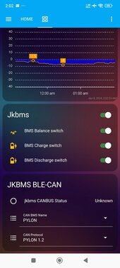
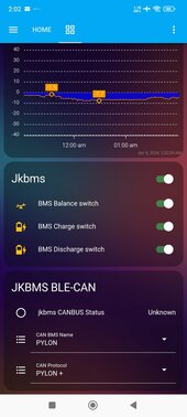
While the BMS (the one you are trying to use) is:
View attachment 207632
- Are you sure you are NOT making a Crossover cable by mixing TIA 568A and TIA 568B ?
View attachment 207633
- Did you add the Termination Resistor (120 Ohm) ?
- To check the basic communication if you are on GNU/Linux with some CANbus adapter lying around you could try "cansniff" command part of the "can-utils" package.
That's what I tried here:
https://diysolarforum.com/threads/j...-logic-open-source.79325/page-37#post-1046211
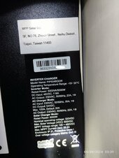
EDIT 1: on your inverter I can see this at
https://www.mppsolar.com/manual/PIP-GEW/3024_5048GEW manual-20230919.pdf
View attachment 207636
So the proper pins if you look at the RJ45 Plug with the locking tab facing DOWN (!!) are the pins on the RIGHT side.
Look at my Deye screenshot for more information (you need to turn the RJ45 Plug 180° to match the RJ45 socket, then the Pin 7+8 of the RJ45 Plug are on the right side [when the RJ45 locking tab is facing DOWN], just like the RJ45 Socket).


") .
.