diy solar

diy solar

Building the sickest ® VAWT ever. Brilliant minds unite please!!

the magnets do not show any signs of heat buildup what so ever.

NO that is not true. I can see some of heat transfer.

But by the time they have rotated it all has cooled down.


NOW this is ! BIG worry for me.

Because if we go full scale like we of course need to. Then there is no more opportunity for the many many things that allowed for these results to propagate to the large scale tests.

I am aware, I will admit that I sometimes did not see it coming.

Let us just just hold on till I am happy with the PMA.
 
Last edited:
and in case yo are wondering why it is soo damned cold there?

well that is because I stopped heating my gym.

So what ever the temp outside is. some of it will be matched by the amount we are leaking.
 
read them and wheep.

1713796808239.png

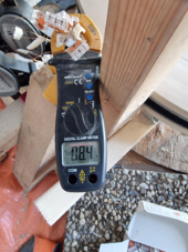
8.4 amps at 9.8 V

1713796905710.png

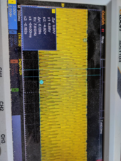
82 watts!!!!

not too shabby for a mere 5x litz 0.4mm wire at 35-70-35 coil now is it?

I just so long to be stood corrected!!


Until such time I am moving forward. Going full scale.
 
Last edited:
82 watts!!!!
Would that it were so simple. The RMS (DC equivalent) value of a sinusoidal AC waveform is 70.7% of half of the peak-to-peak voltage. This is because you also have parts of your waveform that are much less than the peak. So, half of 9.8V is 4.9V, and the RMS voltage is 4.9*0.707=3.5V.

Now the power generated is 3.5V*8.4A=29W. Actually less since you measured the open circuit voltage, not the voltage while under load.

https://www.techtarget.com/whatis/definition/peak-to-peak-pk-pk
 
if you are here for the party then why are you such a party pooper?

hahahaha

nah brother. keep it coming. ok less than 29 watts it is then. I will read up some more but even so.

I think this base line coil is not disappointing is it?
 
so disappointing that I went and checked on how to calculate dc rms based on ac peak voltage in a single phase setting and came to
9.8 vACpeak = vDCrms * SQRT(2)
which works out to 6.92 vDCrms
which in turn works out to a wattage of 58.2 when multiplying by 8.4 amps.
Anyway since this was in an open circuit setting I am going to potentially sacrifice one of my lifep04 cells and hook it up directly to the base line coil and measure both the amps and the vDC at the same time to get things cleared up regarding this.

I fully believe now that pulse charging is not a problem based on the below research paper so all I need is a simple rectifier.
(this study reviews several earlier researches regarding this and no need to translate from Dutch as it is in English)

Should the base line coil be happy to provide too much power I can add another cell in series and just keep adding cells in series one by one until I get a better understanding of what this coil can do.
 
so disappointing that I went and checked on how to calculate dc rms based on ac peak voltage in a single phase setting and came to
9.8 vACpeak = vDCrms * SQRT(2)
which works out to 6.92 vDCrms
which in turn works out to a wattage of 58.2 when multiplying by 8.4 amps.
But your peak isn't 9.8v, your peak-to-peak is 9.8v. You still need to divide by two.
 
But your peak isn't 9.8v, your peak-to-peak is 9.8v. You still need to divide by two.
argg. I both love it it when my superiors are correct all(most off) the time(s) else risk me running after my own tail all the time.

But also hate it as it is slowing me down/ or even preventing me to get to where I want to get.

But this is just a joke of sorts.

I really respect the pushback otherwise we end up with garbage for a whole new generation of unsuspecting readers to just blindly follow.

Anyway Gary, I think you know more about how this stuff works that the internet does because when I started measuing your statment with the setup below I could do not nothing else than flame and admit you are correct.!!
Now do you see how close the word admit is to another one that conveys my emotions? hahah

----


damn{insert characters}....


-----

My lord I hate infuencers!

I'll ask again! :) . How does one protect their offspring these days from this wildfire of nonsense?

Anyway back to the matter at hand.
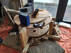
1714055266548.png

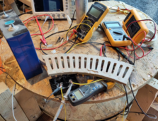
Here we have the most recent configuration preparations for what I think in the meantime is a sane way of tackling this problem.

I have now stored into the freezer the simple method I proposed earlier. Rest assured it will thaw again at one point or another. I guess we all know by know that ideas will mostly be re entertained if not properly laid to rest. Just for the sake of being able to let things go.

Was it easy for me to admit that my wild ideas were misguided?
...
..
No of course not. I hated that. I had hoped to be the next genius out there.
..

did that determine me to understand that that is is only a bonus which we should not expect and that the goal should remain the goal?
(without a second thought) of course. lets get this on. where ever this leads us. I will take my pride from the fact that I was even able to get things done with the help of so many of you.

-----

What we have here is a setup that can measure many data points in a single run. With the exception of the data points to be taken with an open circuit.

Now the start point is a Lifep04 cell single cell, But it is easy enough to add to it in series step by step.

Please scrutinize the following data points I think are relevant for the creation of solid charts.

If this is going to be the new standard then I am a bit sad.

Boy I wanted it to be just simple!!! even though I knew it was going to be HARD. I just once again thought that maybe with a little weird thinking perhaps things could become less difficult.

Hahha. well at least I keep trying.

Here goes

* motor Hz
* (open circuit) (Hz) while at vAC (below)
* (open circuit) vAC
* (closed circuit) vDC (after rectification)
* (closed circuit) aDC (after rectification)
* Coil temp (celsuis)

Now I already know I forgot one or 2. Please help me out here.
 
Last edited:
So I thought and go with 15 coil legs per unit rather than more as to make it more manageable to actually have them play nice while in service.

I do think you are going to have to take my word for it else risk to stand challenged by me ;)

Now given my reserves have just recently been recharged again. I would advice to only do so if one has a good point. :)

You see that I today I found a new way of measure coil lengths to be able to wind them in larger strings.

Well here we go

1714064846616.png


Ok sure I will have to admit that this casting is not the best. But even so it has regenerated my reserves again.
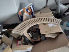
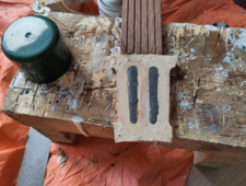
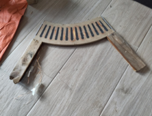
this is a 35-(13 x 70) - 35 coil @ 5 x 0.4mm litz. 10mm thickness (roughly. Boy this cast did not work out well at all :) )

even so.

Ready and waiting. Poised to strike!!
 
Last edited:
ohh and of course I have a new hot topic.

The larger the resistance is in a wire. the more an iron filled core will do in terms of field enhancement.

this is my bold claim. And I am sticking to it for the time being.
 
I respect that it is a jungle in the picture.

But that is because I am not a realtor trying to sell a home.

I am a guy that tries to convey what is going on here.

Now I do welcome anyone that would like to see some things changed. like make it more obvious which wire is going where and stuff like that.

Other than that. This is the best I can do, for now until more education.

And still I hope it will be read them and cry in joy.
 
ohh and of course I have a new hot topic.

The larger the resistance is in a wire. the more an iron filled core will do in terms of field enhancement.

this is my bold claim. And I am sticking to it for the time being.
So I also still do not understand it.

Please let me explain as far as I can. I also do not understand it... yet..

So when we take our 29 leg coil and fill a few cores with iron.

1714120698092.png

Then there is an increase of field considerably higher than without.

one wire
without: 0.89 mT
with: 1.3 mT

5 wires
without: 2.15
with: 4

I realize that I am soo all over the place with my readings but that is simply because I still have no clue of how to operate my CV/CC. try as I might this thing just operates above my pay grade. How ever much I try to persuade. nee coerce. nee bribe it to cooperate.

Now if we do the same on our old base line coil (I say old because it was not up to the task to pulse charge even a single cell so now we have our new coil)

1714121175394.png

then we get only like 20% increase something to that effect only.

But in order to keep things installable this is what we will use now as the base line

1714121222993.png
 
arggg!!!
poised to strike I said? out loud? hahahah


Well that was an overstatement if I ever made one.

These iron filled cores make the cast bend when in between the magnets

So back to the drawing table it is :(
 
Last edited:
well since we are on the topic of bending all options we have to deal with it converge again.

i really wished making coils at are actually any good was easy!!

so we are still all in agreement that we need iron filled cores yes?
I certainly think so if we want to end up with coils that have a chance of being refereed.

Ok well then we have this bending that can happen when the one casting the coils is just not experienced in making them both strong and happy to dissipate heat all in a single casting. Yes I know I need more practice but the problem is that staying with PU will make for the coils to melt at 86 degrees C.
Going with high temp epoxy will make for that I will lose my mold pieces and spend the rest of the decade printing and post curing.

Now I have all kinds of things I can try to work around most of the issues and all have their pro's and con's. It is just a little frustrating that I was happy telling that I had found new hope again (those reserves that were depleting and got replenished) to now once again look at the sheer amount of aspects to consider if we want to do this right.

Yeah sure one could argue just use one of those templates/blueprints.

Well I will once I know I am on the wrong track. For now I think what we are doing here is laying some new ground rules as to how to measure ones magnet/coil configuration if we ever need to be able to take them seriously.

Hence I am still at this.

This makes me think of this scene of this film in where this famous line comes from.
"get to the chopper"

in that same film is a badly damaged team member that says
"I can make it"

But in my case I actually only have mental reservations not physical so I will repeat.

"I can make it" :)
hahahah
 
Last edited:
you know what would really help here?

Just some base line figures from one of the authors of those books that keep being inserted here.

Shall I just go and ask? I do hear especially Mr Piggot is open to dialogue if one can be on point.

Well do we think I can be ? I am not sure here gang.

How do I formulate this question then?
 
yes. let us first lay ground rules on our lab bench yes?

mine is an entry level. it can do 32v at 10.1 amp.

Now how do we get this cheap unit to do what it needs to do to start making sense of this all?

Now I am willing to admit I just used it wrong or buy a more respectable version of this concept if we at least first establish that this one is indeed the reason I am just all over the place with my readings.
 
I am sorry to have to report that I will put into the freezer for now the iron enhanced cores.

My craftsmanship is simply not good enough as I keep, both literately and figuratively, bumping into problems.

Ok so now the coil seems stable after some tweaks and making sure we do not hit the temp limit of the PU resin.

Now the whole of the rotor disks just do not want to not move while being persuaded by the iron powder cores.

I will have to, begrudgingly, admit that I just do not have the skills yet to pull of this feat in a DIY setting.

I will go ahead and remove the iron cores as to be able to finally produce some data I have been talking about for more than actually producing said data.
Yeah I know :(
It is just not right and I feel the shame. I am not even kidding here.

Iron cores might be back when I either have learned more on how to DIY things properly or just go less radius while increasing rotation speed.
 
BTW dear readers. please remember that in essence this is still a community project.

I am sure I have said it like a million times before but without many great suggestions we would not have at least a glimpse of what might become to begin with.

Sure the heavy lifting is local but I am still very very much hoping for someone somewhere to swoop in and give a suggestion that seals the deal.

Getting the rotors to just stay put. How ever much bribery is being used to persuade them to snap to the iron cores.

I mean some craftsman out there surely dealt with this problem before yes?

And now I start to side with Hedges. His long held dislike for OSB I never could put my finger on.

Well in the meantime I think I can. From type 3 and above it is great for resisting shearing forces. Not at all so much when it comes to "bending" forces. As to say the forces applied perpendicular to how the strands are oriented.
 
Last edited:
If you have ever showed how you actually hold the coils down, I missed it in the remainder of the discussion. I don't see any bosses cast into the coil sections that might (for example) allow an occasional screw to secure them to the framework.
 
Back
Top