brandnewb
Going for serious. starting as newb
--- TL;DR update
UPDATE: 22/04/2024
82 wattage potential for a 35-70--35 coil? Let us hope I did not make a mistake.

 diysolarforum.com
I mean when we then extrapolate then yeah this PMA will kick ass hard. If only I did not mistake somewhere.
------------------
UPDATE: 08/04/2024
Hold on to your buttocks!!

 diysolarforum.com
UPDATE: 25/03/2024
please allow me to be a little Nordic.
Can one please distill all new information into a well defined graph supporting ones intentions when one comes here as a new comer adding new information to the cause.
In case that is a little challenging then a well respected flow of keeping things cool would be, is to recognize that our scenario is far less generic than one might gather at first glance.
--------------------------------
we are getting somewhere now. managed to reduce diameter while increasing flux to play with. I am not yet so far as to give output data. Only predictions can be found in this long thread.
ALSO!! (unfunded) snag remarks are NOT welcome here. constructive criticisms is both welcome and needed though.
I think I finally cracked the code. I am going this route

 diysolarforum.com
UPDATE: 20/01/2024
We are going IR!

UPDATE: 12/10/22
16 volts with 800 winds at 60 rpm without iron powder.
I think the title is becoming more and more relevant.

 diysolarforum.com
UPDATE: see things spinning

 diysolarforum.com
UPDATE: witness the sickest coils ever

 diysolarforum.com
--- end edit
Ok boys and girls,
After having seen many commercial turbines fail, underperform and otherwise not life up to expectation I have decided it is time to put an end to this sad state of affairs.
For an analysis of my latest disappointment please see

 diysolarforum.com
I see no other option than to take it upon my self to DIY a VAWT and alternator that actually works i.e. that outputs an insane ® amount of power at low (safe) rpm.But as you might have guessed by the title I probably can't do it alone. The title has changed but that is not to say I do not need/respect help
I will be referring to the components in the thread above with a prefix of crap. So when I say e.g. crap coil I mean the coil of that cheap Chinese alternator.
The crap stator is a 3 phase 36 coil (12 coils per phase) radial flux variant.
The crap coils consist roughly of 68 - 70 winds (+-136 - 140 turns) at +- 16cm each totaling of about 11m per coil x 12 coils = +-132m of copper wire per phase.
The crap wire it self has a diameter of 0.4mm.
There are 12 poles in the form of sector magnets with an, as of yet, unknown tesla strength. I will be figuring out a way to measure it sooner or later. I changed my mind, I will not try that as it will mean extra equipment that I am not interested in for now. NO the magnets we are using here are far!!!! more powerful
I will be using an rpm for testing of 60 so that I can easily spin the alternator by hand with a reasonable consistency. At that rpm I hope to get a usable output already if at all possible but in any case not faster than 120 rpm, which should output at insane (TM) levels, else risk injury or worse if the, yet to be constructed, blades fling off.
when spining the crap alternator at 60 rpm there will be a 6 Hz oscillation in the crap coils. With the crap rotor having a diameter of 8 cm.
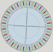
Now here comes the fun part. I am contemplating building the following 3 phase axial flux alternator

Having 48 x 60x10x5mm magnetic poles at a 35 - 40 cm radius.
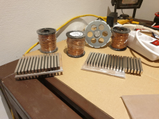
I have 1mm enameled copper wire that is about 71m long.
1 winding (2 turns) of each coils is about 30cm totaling in about3.6 7.2 meters of 1mm coil wire per phase per 1 winding.
The alternator will produce an oscillation of 24 Hz while running at the reference speed of 60 rpm.
Now should I try and match or supersede the total crap phase wire length or should +- 71m be adequate for the new phase coil wire length?
UPDATE: 22/04/2024
82 wattage potential for a 35-70--35 coil? Let us hope I did not make a mistake.

Building the sickest ® VAWT ever. Brilliant minds unite please!!
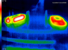
the magnets do not show any signs of heat buildup what so ever. NO that is not true. I can see some of heat transfer. But by the time they have rotated it all has cooled down. NOW this is ! BIG worry for me. Because if we go full scale like we of course need to. Then there is no more...
I mean when we then extrapolate then yeah this PMA will kick ass hard. If only I did not mistake somewhere.
------------------
UPDATE: 08/04/2024
Hold on to your buttocks!!

Building the sickest ® VAWT ever. Brilliant minds unite please!!
I give up. even this most recent coil with only the legs filled with iron powder simply does not produce an voltage enhancing effect. if anything it actually helps the field to circumvent the coil wires as it now can wiggle around the wires rather than through them. Blue channel still is the...
UPDATE: 25/03/2024
please allow me to be a little Nordic.
Can one please distill all new information into a well defined graph supporting ones intentions when one comes here as a new comer adding new information to the cause.
In case that is a little challenging then a well respected flow of keeping things cool would be, is to recognize that our scenario is far less generic than one might gather at first glance.
--------------------------------
we are getting somewhere now. managed to reduce diameter while increasing flux to play with. I am not yet so far as to give output data. Only predictions can be found in this long thread.
ALSO!! (unfunded) snag remarks are NOT welcome here. constructive criticisms is both welcome and needed though.
I think I finally cracked the code. I am going this route

Building the sickest ® VAWT ever. Brilliant minds unite please!!
Nothing technical to add, just a bit of psychology. The vast majority of people here are technical types and as such we all have social "issues" in dealing with other people. (I don't know any competent engineers I wouldn't put on the autism spectrum, myself included.). Add on to that that...
UPDATE: 20/01/2024
We are going IR!

UPDATE: 12/10/22
16 volts with 800 winds at 60 rpm without iron powder.
I think the title is becoming more and more relevant.

Building the sickest ® VAWT ever. Brilliant minds unite please!!
Yesterday was my 1st anniversary here. Let's see how much damage I can do towards the next ;) also I am a bit sad. I am not shy to tell. When I first started here a year ago I was a newb. *cough* still am. After the cheap Chinese wind turbine debacle thread I knew all that was left is to...
UPDATE: see things spinning

Building the sickest ® VAWT ever. Brilliant minds unite please!!
I think so. Coil of wire with AC applied should measure it too, but then there would be resistive losses in the wire. Moving a magnet, only drag from air. 3600 RPM would be 60 Hz.
UPDATE: witness the sickest coils ever

Building the sickest ® VAWT ever. Brilliant minds unite please!!
Like I said, it is OK to scoff. I am reduced at work to just doing real-time software and hardware integration, so I let the *real* engineers do the math. I'm always impressed by the experts who really know their stuff in their area, but I am equally impressed by those who have enough...
--- end edit
Ok boys and girls,
After having seen many commercial turbines fail, underperform and otherwise not life up to expectation I have decided it is time to put an end to this sad state of affairs.
For an analysis of my latest disappointment please see

Cheap chinese horizontal wind turbine, an in depth exploration.
--- Begin edit Please do not reference to unproven products. A proven product should at least have an rpm vs some kind of output graph with warranties. for the building of a DIY alternator that actually works please see...
I see no other option than to take it upon my self to DIY a VAWT and alternator that actually works i.e. that outputs an insane ® amount of power at low (safe) rpm.
I will be referring to the components in the thread above with a prefix of crap. So when I say e.g. crap coil I mean the coil of that cheap Chinese alternator.
The crap stator is a 3 phase 36 coil (12 coils per phase) radial flux variant.
The crap coils consist roughly of 68 - 70 winds (+-136 - 140 turns) at +- 16cm each totaling of about 11m per coil x 12 coils = +-132m of copper wire per phase.
The crap wire it self has a diameter of 0.4mm.
There are 12 poles in the form of sector magnets with an, as of yet, unknown tesla strength.
I will be using an rpm for testing of 60 so that I can easily spin the alternator by hand with a reasonable consistency. At that rpm I hope to get a usable output already if at all possible but in any case not faster than 120 rpm, which should output at insane (TM) levels, else risk injury or worse if the, yet to be constructed, blades fling off.
when spining the crap alternator at 60 rpm there will be a 6 Hz oscillation in the crap coils. With the crap rotor having a diameter of 8 cm.
Now here comes the fun part. I am contemplating building the following 3 phase axial flux alternator

Having 48 x 60x10x5mm magnetic poles at a 35 - 40 cm radius.
I have 1mm enameled copper wire that is about 71m long.
1 winding (2 turns) of each coils is about 30cm totaling in about
The alternator will produce an oscillation of 24 Hz while running at the reference speed of 60 rpm.
Now should I try and match or supersede the total crap phase wire length or should +- 71m be adequate for the new phase coil wire length?
Last edited:


