brandnewb
Going for serious. starting as newb

yes agreed, this modeling is below my abilities.
well bite me. I am on a linux system now and for the time being can not use my software of choice.
But can one see where I am aiming at?


ahh good to know brother that you are of the growing type. I myself have started growing as well. Yet again like with all of my endevours I start with absolutely no idea of what I am doing.My citrus trees are not happy.
can you please elaborate?
I mean given that MPPT charge controllers can basically handle any given input to charge any given battery array.
Then that means all bets are off and it is back to where this journey all started. building the sickest ever!!!
@Warpspeed please resurface once more. I respect that you have das boat like sub surface abilities but now more than anytime in history I hope you are willing to come to the surface again and give some expert feedback on my most radical idea yet.But can one see where I am aiming at?
the best thing in this pdf is, bar none, the made in America quote
")
ok I tried brother to wade through it. Yet I shipwreck once again.Slide 23, rated amps (watts) vs. max input volts (model). Also a dollar premium for the 250V model, which handles lowest current.
Probably fewer amps for a given voltage because that is the trade-off in transistors, and cost due to higher voltage capacitors (I would guess).
This would likely not be the case if the higher voltage models were also meant only for higher voltage batteries (fewer amps needed for same wattage.) Which is why GT PV inverters and HV battery inverters are light weight and inexpensive.
Page 18 mentions Clipper. I think I've seen circuit schematics somewhere.
I think I can do that. I mean all I need to do then is first setup the turbine and see it spin at 3m/s. then design the alternator to give at least 48V+30$ at that rpm. I really do not think that things will get so out of hand that the turbine will start spinning so fast under load that it will go above 150V.If your max voltage remains low enough for the Classic 150, it is the better deal - lower cost and higher output.
I think clipperOr buy "Clipper"
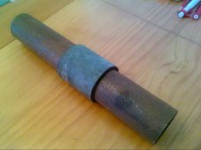
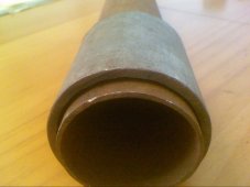
Here is a piece of two inch water pipe, and a rusty old piece of two inch exhaust tubing I found out in the shed.
Its a nice easy sloppy fit, about 2mm clearance by eye.
That exhaust tubing is terribly thin, only about 1.6mm, but you can get much larger diameters and wall thicknesses in inch sizes.
thanks. I get the idea.