diy solar

diy solar

Building the sickest ® VAWT ever. Brilliant minds unite please!!

just thought of another reason to increase the rpm considerably.

because then the yet to be build fans attached in between the rotors behind the coils will cool the coils much more then at slower speeds.
 
it is confirmed. the magnets are not spaced evenly apart on the rotor disks.

my rushing and just overall poor experience with double checking things before I leap in made it that the distance and position is just ever so slightly out of sync.

going at it!
 
I tried AI again but am unable yet to ask the correct questions.

Is there anyone that can help with figuring out the loss of torque when using timing belt pulleys to increase the RPM of the PMA. Or maybe more easy to help define questions to steer AI into a well defined path so that it can only focus on number crunching rather than being creative.
 
it is confirmed. the magnets are not spaced evenly apart on the rotor disks.

my rushing and just overall poor experience with double checking things before I leap in made it that the distance and position is just ever so slightly out of sync.

going at it!
hahah what a fool I am thinking I can get the real world as perfect as a digital model.

Ain't gonna happen!! never can. I do not care how much machining prowess one can throw at this but there are always . always sub measurable differences. in my case those differences are detectable by the human eye :(

I was able though to make it far more consistent but now we have only 2 magnets rather incorrectly spaced.
In my books this is called best effort.
 
Last edited:
WT is on a 12 mtr hinged tower. I should point out that the over 40Kw day was a 50Mph day with 70MPH gusts. Wind today about 25MPH. Today solar PV has done around 6K and the wind had made 14Kw in 14 hrs. I'm not obsessed with the daily data as I have too many things to get on with. So no I don't have graphs. When I started my journey we had an ancient Lister 3cl 12KVa genny. and nowt else. What I do keep records of is my fuel costs year on year for 20 yrs. The satisfaction for me is getting that spend down. I'll never expect to be 100% RE but this year I changed to an LPG powered genset., Dearer to run than the Lister but no oil or smell and service costs are lower.

Adjusted for inflation since 2001 Diesel costs 1st year 3000 Litre @ 80p/L = £2400
Last year on Diesel 2023 400 Litre @80p = £ 320

Should point out that the house is medium size 2500 sq ft. 1000ft up a hill and exposed. Unlike some off grid set ups I like to live comfortable so we have all the usual kit, ie automatic washing machine, dish washer, 3 deep freezes, fridge, LED lights all round. Wet, pumped UFH. House is always warm. I have recently installed a 3Kw ASHP to supplement the UFH. This ASHP is a dump load so if genny runs or the WT has topped off the batteries the ASHP starts up to burn of the excess. So the ASHP is effectivley running for free. Love it.
please allow me to be a little Nordic.

Can you please distill this all into a well defined graph supporting your intention when you came in here?
In case that is a little challenging then a well respected flow of keeping things cool would be, is to recognize that our scenario is far less generic than one might gather at first glance.
 
I'm very sorry but I don't know what you mean about Nordic.

I envy you your offgrid status. especially for so long. if only I could ever get there. Start with the 1st step. and then the 2nd etc, it's theonly way.

My intention when I came in here was to offer assistance based on real life experience. I don't know how to graph this.

You stated previously. The issue with said books is that they are about HAWTs in areas where they can spin really fast without the fear of killing someone when something unexpected happens.

In my world, wind turbines do not generally throw bits off killing people. That is said assuming that the desgn is correct and the construction is to appropriate standards. So if you can't do decent welding and your WT fails it's down to you not the design. WT don't usually spin so fast as to self destruct, as long as they are "loaded" the faster they turn the greater the resistance from the alternator which acts as brake. Many WT fail due to the tower collapsing. Although tower failure could be a consequence of a badly balanced unit causing excess vibration.

I should imagine you have been recording the local wind speed for the last couple of years so you should have a very accurate picture of your potential power source.

Given your local restriction on size of WT why not put up the largest WT you are allowed and run it as a trial. Dependant on results could you not put up a number of small units to harvest the wind.
 
I am hesitant to entertain such experiments because of physics and the Betz limit :(

nah my dear new friend. I will focus on what I need to focus on until such time we are presented with a whole new way of tackling this goal.
 
again it is official. I am going to put more pressure towards leaving this sketchup non parametric style of modeling.

It is easy to get started with so that is why I did.

But sooner or later one is going to reach the limits like I am doing now.

Now what one needs is parametric modeling. Sure it is far less easy on the easy to be intimidated. But one needs to bite through. trust me!!

I will give blender another chance as now it has add-ons catered to just this. Especially since my kid expressed interest in what I was doing while modeling. Now no sane person will ever consider teaching their offspring this retarded sketchup setup I have.

Anyway? why this rant?

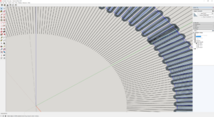
Because I am still figuring out how wide the coils could be in theory.

I am inching closer to where I need to get but the time it takes is just too much time. It should have been simple like just change parameters.

1711381458850.png
 
Last edited:
now please do not hold your breath as I do not expect this latest coil to do wonders.

1711394725445.png

it is a 150, 300, 150 configuration at 0.4mm. but there was soo much space left in terms of thickness that I am beginning to think again I can make it without gears. even at 0.71mm wires.
Not that I want that per see as we would be then neglecting all the benefits we came up with recently at the higher frequencies.

but come on gang. does not this look like a gem in the rough? with even +90% iron cores to boost.


I am going to sleep early as tomorrow I have a field trip to attend with my kid. But please rest assured that I will be revisiting this.
 
I'm very sorry but I don't know what you mean about Nordic.

I envy you your offgrid status. especially for so long. if only I could ever get there. Start with the 1st step. and then the 2nd etc, it's theonly way.

My intention when I came in here was to offer assistance based on real life experience. I don't know how to graph this.

You stated previously. The issue with said books is that they are about HAWTs in areas where they can spin really fast without the fear of killing someone when something unexpected happens.

In my world, wind turbines do not generally throw bits off killing people. That is said assuming that the desgn is correct and the construction is to appropriate standards. So if you can't do decent welding and your WT fails it's down to you not the design. WT don't usually spin so fast as to self destruct, as long as they are "loaded" the faster they turn the greater the resistance from the alternator which acts as brake. Many WT fail due to the tower collapsing. Although tower failure could be a consequence of a badly balanced unit causing excess vibration.

I should imagine you have been recording the local wind speed for the last couple of years so you should have a very accurate picture of your potential power source.

Given your local restriction on size of WT why not put up the largest WT you are allowed and run it as a trial. Dependant on results could you not put up a number of small units to harvest the wind.
You got me there my new friend.
I am worried that my lack of craftsmanship will lead to disaster.

Once I am confident I can make a lift type turbine not fly apart and have it float far away from where humans might be hit when a blade does fling off and breaks it's tether non the less.
Then I will go lift type.

The only thing that might get in the way of this goal is when air wheels ® become a reality.

And with going Nordic I meant just full out honesty :) I will admit that I might have historical details all mangled up but I was thinking of the Vicans that, in my mind, never made false pretense. They just went at it :)

But then again. The Dutch are also not known for beating around the bush too much if at all :)
And they used to be known for not being prudes. Well I can tell you a trivia by now. Our nation is starting to look like they invented being prude.
arrrggggg
 
Last edited:
also gang. I am running into rather serious stability issues with the current PoC PMA. it is just too wobbly.

I am going at it really hard to make at least this new coil being testable with the same 17mm spacing between rotor disk magnets.

The result might be horrific to look at but at least it can give much needed data.

I am still waiting for the motor to arrive but am printing the pullies as we speak

1711536065137.png

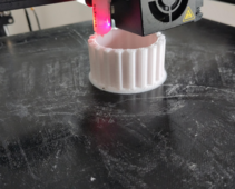
I am now using a T10 rather then the earlier T5
This means I can keep using a 1mm nozzle. The amount of time this saves is incredible.

for a 16mm high 100mm diam test print from 9+ hours using a 0.2mm nozzle to 1hour using a 1mm nozzle.


this is a 32mm high test print with flanges as now I also changed from a 16mm timing belt to a 32 one as I can already imagine that 16mm is less ideal to distribute raw power over than 32mm.
 
so here I finally think I can demonstrate the tiny bit of extra voltage producing capabilities of iron filled coil legs.

And I need to make a correction as the latest coil was double wired as the one before it. This means 200, 400, 200. not 150, 300, 150.

Both coils were ran in the same conditions as they were ran in parallel.
17mm spacing between the magnets on opposite disks.

the coils
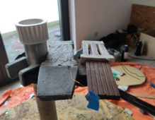
1711539695431.png
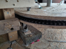
the disks we already know how they are but to make sure things do not get bumping up or down then I used this.
1711539889095.png
hahah look how almost , almost, perfect the magnets are spaced now. But they really are not :( there is one spot in where 2 of them show clear signs of misalignment as that is where the 2 half circles meet.
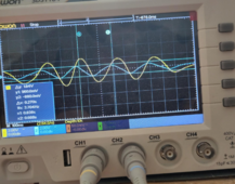
Now let us look at what the previous 100,200,100 coil did without any iron added.
1711540206984.png

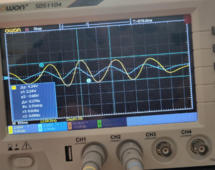
Now let us look at what the 200, 400, 200 did with iron powder added.
Mind you they are both running in the same run.
1711540281833.png

How ever slightly. The voltage generation ability seems in this early stage of testing to be more than doubled. Doubled sure because of the double amount of wires. But more than that might be because of the iron powder added.

Now once again this could have been anything mundane. Like not both coils are equally well positioned. I will admit that.

But that does not mean I should not try and pursue this line of thinking. Only when it is established without a doubt that adding iron powder to the coil legs (never mind the cores of the coils) does more harm than good then it is time to abandon the concept agreed?
 
Last edited:
But that does not mean I should not try and pursue this line of thinking. Only when it is established without a doubt that adding iron powder to the coil legs (never mind the cores of the coils) does more harm than good then it is time to abandon the concept agreed?
wow, there is no way yet I see the reason to abandon this line of thinking. I earlier totally neglected the heat dissipation enhancement it will bring.

Now I am facing rather touch engineering challenges to keep rotor disks of this size stable when attracted to iron filled coils. I thought this a possibility from the start as to be expected and now it is coming to fruition.

arggg.

But then again if we have enough data to support this setup might be worthwhile then there is nothing holding me back to employ a professional to make a disk rigid enough.

But that would defeat the whole DIY concept.

I am borderline sad at the moment. I might have to scale things down again and then go stacking 4 disks of 48 magnets with each having in between a single phase.
 
Last edited:
ahh no strike that. earlier one of the contributors has made a very low tech solution suggestion to this problem . Let us just tether the disk on strings then hanging from the central column.
 
Now I am facing rather touch engineering challenges to keep rotor disks of this size stable when attracted to iron filled coils. I thought this a possibility from the start as to be expected and now it is coming to fruition.

Air bearings? Maglev?
But traditionally just ball bearings and rigid structure.

Those dolly wheels won't support the speed you need for good production.
 
Those dolly wheels won't support the speed you need for good production.
which speed are you referring to? in this scenario we are still talking 3.7Hz so the speed/velocity you might be referring to is going to be really really low

but i agree that this proof of concept setup should not be allowed to be ever taken into service. Just soo many things unstable about it
 
Last edited:
this must be the coolest idea to be ever conjured!!!!

and when we think about it? why not?

incredibility cool thoughts you have bro!!

one day I hope you and I get to grow old on a shared land and use our respective prowess to make more than due.

I am just not sure we are ever going to agree on where this fantasia land should be located :(
 
The place where Transition Training is mandatory?
Or the one where Brothels are a Tourist Attraction?

Hmm, difficult decision.


I envision passive, not closed-loop active, maglev.
 
Or the one where Brothels are a Tourist Attraction?
guilty as charged! Although I was born there now I left that hell hole for quite a while.

The place where Transition Training is mandatory?

Hahahh I have no clue still. I tried Ai to unraffle what you meant there but it just comes up with

"""Transition Training" in aviation is a form of specialized training required for pilots moving to fly aircraft that are more complex or have higher performance than what they're used to""
Even though I told it to take into account the location that comment came from which I will not share here for obvious reasons.

Let us envision Bali - Indonesia. The only part of Indonesia that is still resisting the spread of lifestyles not tolerant to those that are not similar.

Even though I am going there because my family is Indonesian and I want to settle down somewhere close by and in relative peace. I did find in my research leading up to that move that the locals of Bali give it 40 maybe 50 years before even they have buckled of the relentless pressure of fanatics trying to take over (not only there but indeed the rest of the world)
And also truth be told that it is nothing like the travel brochures are making it out to be. Nah it is a dump near sea level. I am aiming higher up the mountains. There it can indeed still be calm and serine.

{1}hahah found it!!!. yeah no Bali is still on top of mind :) {/1}
 
Last edited:
Ok back to the topic at hand.

While still waiting for the motor to arrive to make detailed charts at various frequencies I already ran into a new issue regarding the T10 timing belt pulleys.

You see that the current central column of the PoC PMA is 50mm diam. So that means that I need a certain minimal amount of teeth for the pulley to still be of type T10.

But if I want to then have the drive (turbine) rotate 4 times slower I will need 4 times that teeth there. Then the diameter of that pulley would become HUGE!. Not at all interested in entertaining that avenue.

So I am going to reduce the column diam of the PMA so that I can have a 1:4 ratio that makes more sense in terms of diameters of said pulleys.

The reasoning why I am going for a 4 times increase in rotational speed as opposed to the turbine is because when I do finally go lift type blades then I expect the turbine to rotate 4 times faster than it is doing now.
And then things can become a direct drive again.
I love it when a plan comes together. Famous words of RIP George Peppard. Hanibal from the A-Team.
 
Back
Top