diy solar

diy solar

Inverter over voltage and shutdown

The Batterys have nominal Voltage of 48V (15 cells), i want to charge only to ~80% for longer durability.

Bulk Voltage Point 51.0V and Floating Voltage 50.5V.
Ok, 51V 15 cell is 3.4V per cell, and that is 100% full charge, if any cells are out of balance, they could be hitting bms disconnect voltage.
I would make 50.5 the bulk, and float at 50.0
 
Ok, 51V 15 cell is 3.4V per cell, and that is 100% full charge, if any cells are out of balance, they could be hitting bms disconnect voltage.
I would make 50.5 the bulk, and float at 50.0
Did you ever get this problem fixed with the new settings? I am having the same problem with a 10kw PowMr. As soon as the batteries reach full charge the charge voltage spikes and trips the inverter. Thanks!
 
No, the issue is still there. I am talking with the manufacturer about this problem. But it seems that they have no idea.
I can tell, when you cut one PV String, then everything works fine. I think the two MPPT have a problem with the current regulation against each other. When the Battery is full, then goes the excess Power in the DC Link Voltage..
I should make a video of the case to the manufacturer.
But first I have to wait for sunny weather.
 
I get a new control Board from the manufacturer.
Now i have to wait, the delivery time from China are not the best ;)
in the Link
there is a video from my problem..
and attach a pictures from the time depending.
 

Attachments

  • Screenshot_20240513_180644_Energy-Mate.jpg
    Screenshot_20240513_180644_Energy-Mate.jpg
    45.5 KB · Views: 2
My problem is the fluctuating output voltage, which causes the output power to fluctuate. The battery constantly fluctuates from +20A to -20A every 1-3 seconds.
The Problem occurs when the Solarpower is high and die Battery becomes full charged (floating Voltage)

What charge controller? (model number, link to data sheet) Swinging between +20A and -20A sounds like 40A PWM charge controller, with 20A load presented by inverter.
 
Thats the Components that i am using:

the inverter/charger:

the Battery:

Do you think i should make a Equalization Process? If yes, what parameters (voltage) are necessery for my device?
 
PV 90 to 450VDC, that is MPPT not PWM.

The toggling between +/-20A is suspicious. Maybe the battery is hitting high voltage disconnect (for charging), and then discharging back down.

Both battery and inverter/charger from same brand, so they ought to have settings that work together.

"Battery Equalization" (page 26 of manual) is about flooded lead-acid batteries.
You have lithium, so not applicable. Instead, lithium battery has BMS which electronically charges or discharges individual cells to get them balanced.

Battery manual page 13 mentions BMS and RS-485 communications with inverter.

Inverter manual .pdf I can't search for text. Haven't found reference to battery communications or lithium. Specs only mention Flooded, AGM, Gel. Is there a data connection to the battery? I see it does have RJ45 for RS-232 or RS-485.

Read the manual cover to cover, see if it says how to get communication going with battery. Ask the vendor how to do that. Or if there are VRLA (AGM) settings you should use with the LiFePO4 battery. It probably does communicate, might be plug-and-play but I don't know.
 
I've gotten the inverter and battery to communicate so far. I tried all connections (CAN/RS485) and tested all protocols. However, the inverter did not respond to the settings. That's why I work with self-defined parameters. 50.4V float (want to limit to 80%) and 51V bulk. I throttled the charging current to 30A.
 
51V vs. 54.75V from data sheet.

That may be around knee of the curve; 80% is hard to hit. May or may not access capacity short term, may not allow BMS to balance longer term.

54.75V/15s = 3.65V, full voltage many vendors suggest. People on the forum use that just once during parallel top-balancing.
51V/15s = 3.4V, probably fine, but 3.5V or 3.55V might give more consistent SoC and better re-balancing.

Doesn't see to me like those would explain any issues.

Oh, I see Supervstech who has more experience in this than me already addressed it, suggested lower not higher.

How long have you been running the system?
Are you able to query battery and see voltage of each cell? I'm wondering if it is imbalanced and some cells are running to over voltage cutout.
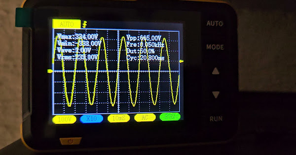
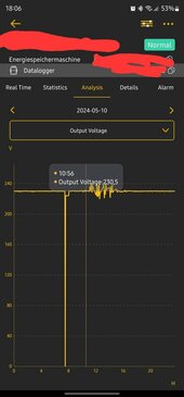
Don't know, but thinking issue is BMS disconnecting battery from your inverter. Just a guess, with only AC voltage out to go by.

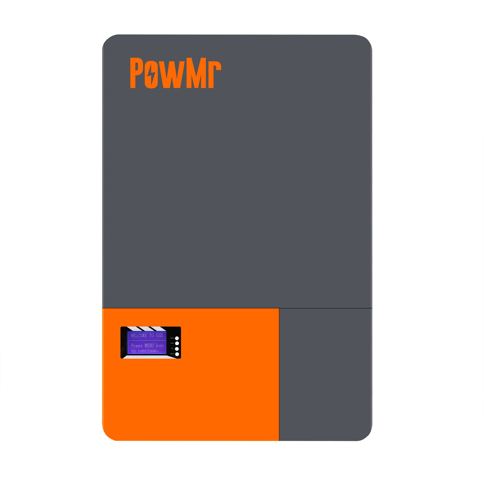
SKU: POW-LIO48200-15S (the 15s, not 16s)

8. Technical parameter list Model LIO48100-15S LIO48200-15S LIO48100-16S LIO48200-16S Array Mode 15S 15S 16S 16S Nominal Energy (KWh) ≥4.8 ≥9.6 ≥5.0 ≥10.0 Nominal Voltage (V) 48 48 51.2 51.2 Charge Voltage (V) 54.75 54.75 58.4 58.4 Discharge Cut-off Voltage (V) 40 40 42 42 Standard Charging Current(A) 20 40 20 40 Max.Continuous Charging Current (A) 100 100 100 100 Max.Continuous Discharging Curent (A) 100 100 100 100

1715702241244.png
 
The Battery and inverter are running no longer than 3 Weeks, but always with this issue..
i can see every cell in the bms menu from the battery. They are all fine balanced and no Cell comes above 3,4V.
But there is an unusual fact that the specified charging voltage of 54.75V cannot be remotely achieved. From around 51.7V the BMS switches off with overvoltage protection.

This week I'll try using capacitors in the DC circuit to smooth out the DC voltage fluctuations.
 
Back
Top