diy solar

diy solar

Diagram Check, 400 watt RV system

chrism33

New Member
Joined
Jun 5, 2024
Messages
5
Location
Michigan
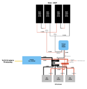
Can you guys check my diagram for issues? I'm getting conflicting info. Just trying to have a simple system when boon docking a couple times a year to run laptops and internet.

400 watt on roof of RV
305 ah battery bank
Victron 1200va, 1000 watt inverter, connecting to shore power on RV, turning off RV converter when hooked this way.
Shunt
150/30 viltron solar controller

Gauge size and fuses were my main concern (unless im missing something)

-Chris
 

Attachments

  • Solar : Camper Wiring Diagram.pdf
    485.9 KB · Views: 13
I would love to check your document. Can you post a picture of it in the post. I'd like to see how you isolate the 1200 VA from the shore power.
 
I used 4/0 for a 12 volt 2000 watt inverter. 2 AWG is pushing it, especially with a low voltage cutoff of 10 volts, pulling 200 amps for power + 15% losses making it 230 amps. 2 AWG welding wire may list a maximum amperage that high, but 4/0 actually has ampacity listed for 230 amps.

The 125 amp fuse for a 2000 watt inverter is way oversized and will blow if you use this to the full potential.

I like the idea of a cutoff for the panels. I use it a lot for putting the RV in storage and troubleshooting.

For the battery, recommend ANL fusing ABYC rated for main battery protection for non-lithium, and MBRF or Class T for the battery. Each of those options takes up more space than I thought before I built mine.

For your inverter, if you connect to the plug on the inverter, you are likely limited to 15 amps. To get the full 20 amps will need to be hardwired. I hardwired directly to a 50 amp plug and jumpered the hot inputs to L1 / L2. For some reason no other plug combination was working.

Its different to me to see a different number of Busbars for positive and negative, but may work.

A nice thing to add is another fuse box for a separate 12 volt leg. I used this to wire a few lights and a Tire Pressure transmitter.

A 100/30 has the potential to put 30 charging amp to the battery. You could upgrade to 100/50 and you'd have room for more panels later. 100/30 would just limit to you to around 360 charging watts.
 
Here are a few comments…

Get on Victron website and look up what they recommend for cable and fuses size for the 12/2000 inverter- (just a guess 1/0 or 2/0 wire). Go with their recommendation on that wire.

If you get two 200w panels you will need half the mounts- (if they fit).

Design your system so you can add more solar in the future.

Good luck
 
I used 4/0 for a 12 volt 2000 watt inverter. 2 AWG is pushing it, especially with a low voltage cutoff of 10 volts, pulling 200 amps for power + 15% losses making it 230 amps. 2 AWG welding wire may list a maximum amperage that high, but 4/0 actually has ampacity listed for 230 amps.

The 125 amp fuse for a 2000 watt inverter is way oversized and will blow if you use this to the full potential.

I like the idea of a cutoff for the panels. I use it a lot for putting the RV in storage and troubleshooting.

For the battery, recommend ANL fusing ABYC rated for main battery protection for non-lithium, and MBRF or Class T for the battery. Each of those options takes up more space than I thought before I built mine.

For your inverter, if you connect to the plug on the inverter, you are likely limited to 15 amps. To get the full 20 amps will need to be hardwired. I hardwired directly to a 50 amp plug and jumpered the hot inputs to L1 / L2. For some reason no other plug combination was working.

Its different to me to see a different number of Busbars for positive and negative, but may work.

A nice thing to add is another fuse box for a separate 12 volt leg. I used this to wire a few lights and a Tire Pressure transmitter.

A 100/30 has the potential to put 30 charging amp to the battery. You could upgrade to 100/50 and you'd have room for more panels later. 100/30 would just limit to you to around 360 charging watts.

Thanks for your time, Chris.

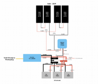
It's technically a 1000 watt inverter (typo in diagram), with 2200 peak. My gut was to go with 2|0 with a 200 amp fuse, but thought that might be overkill?

The 100 amp battery fuses is for the wire, since 4 AWG is rated for 100 amps. I doubt I will be pulling that much with just StarLink, a TV or a laptop. What are your thoughts on 2 AWG with a 125 amp per battery?

Batteries are Lithium. I will look into T class fuses.

15 amps is ok to me. I'm trying to keep it simple.

In one of Wills videos, he recommended bus bars vs paralleling a bunch of batteries, for charging equality. That was the only I thought of to add a shunt into the mix. Adding a bus bar for the batteries, then one for the loads with the shut between them. I'm open to other ideas to include the shunt. (or just paralleling directly on the batteries)

I had a 12v fuse box in the original plans, but at the moment, I have no need for one. So I took it out.

I know I'm maxed on panels with that controller. I originally had 2 batteries and three panels, but added a 4th and another battery because I had room.

Thoughts? or stick to the original?

-Chris

Screenshot 2024-06-06 at 9.57.32 PM.png
 
It's technically a 1000 watt inverter (typo in diagram), with 2200 peak. My gut was to go with 2|0 with a 200 amp fuse, but thought that might be overkill?

The 100 amp battery fuses is for the wire, since 4 AWG is rated for 100 amps. I doubt I will be pulling that much with just StarLink, a TV or a laptop. What are your thoughts on 2 AWG with a 125 amp per battery?
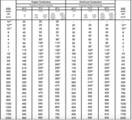
The chart below is what I use to determine wire ampacity. For the 3 batteries in parallel, 2 AWG would be good. If you use 2 AWG, they'd be sharing a load of about 150 amps max when the inverter is on and the batteries are about to have the BMS shut them off at 10 volts each, so they'd unlikely ever see more than 50 amps per battery. The thicker wiring and fuses does let you drop down to two batteries if ever needed, or you could upgrade to a larger inverter later.

The 4 AWG option for the batteries could work.
1717755483851.png
With the inverter being 1000 watts, 2/0 would work, is fine.

The formula I use to size wire is

Fuse and wire size = (Inverter max continuous wattage rating) / (low Voltage DC cutoff) * (Inverter Efficiency Factor) / (1.25 for Safety Factor)

147 Amps=1000 watt inverter / 10 volt low voltage cutoff / 85% efficiency * 1.25 Safety Factor

There's other formulas out there that will lead to smaller wires. Some of those other formulas don't use low voltage cutoff and they won't use a safety factor, which leads to less amps and lower ampacity. Other options are a wire with a much higher insulation rating.
 
The chart below is what I use to determine wire ampacity. For the 3 batteries in parallel, 2 AWG would be good. If you use 2 AWG, they'd be sharing a load of about 150 amps max when the inverter is on and the batteries are about to have the BMS shut them off at 10 volts each, so they'd unlikely ever see more than 50 amps per battery. The thicker wiring and fuses does let you drop down to two batteries if ever needed, or you could upgrade to a larger inverter later.

The 4 AWG option for the batteries could work.
View attachment 220338
With the inverter being 1000 watts, 2/0 would work, is fine.

The formula I use to size wire is

Fuse and wire size = (Inverter max continuous wattage rating) / (low Voltage DC cutoff) * (Inverter Efficiency Factor) / (1.25 for Safety Factor)

147 Amps=1000 watt inverter / 10 volt low voltage cutoff / 85% efficiency * 1.25 Safety Factor

There's other formulas out there that will lead to smaller wires. Some of those other formulas don't use low voltage cutoff and they won't use a safety factor, which leads to less amps and lower ampacity. Other options are a wire with a much higher insulation rating.
Thanks for all the input!
-Chris
 
Here are a few comments…

Get on Victron website and look up what they recommend for cable and fuses size for the 12/2000 inverter- (just a guess 1/0 or 2/0 wire). Go with their recommendation on that wire.

If you get two 200w panels you will need half the mounts- (if they fit).

Design your system so you can add more solar in the future.

Good luck
Well, I went with 2|0, but found out the terminals on the Victron 1200 max out at 2 AWG.
 
Well, I went with 2|0, but found out the terminals on the Victron 1200 max out at 2 AWG.


I typically use this chart taken from the windynation website for welding wire. The wire is rated as 105c so it can carry a higher number of amps without melting the sheath. But, that is 221F if it maxes out. Not enough to start wood on fire or anything, but hotter than I want the wire.

I have the Victron 1200 and I use 2awg in it. Running a heat gun and pulling max amps the wire just gets a little warm after a while.

For fuses - I would put a MRBF 125amp on each battery post. Then I would put a class T inline from the bus bar to the inverter. IF and only if your battery to bus bar leads are over 12in or so I would also put a MRBF or class T at the bus bar end. The idea being if you have a short at the post of one battery the other two will dump their full current into it.

So 250amps into that short from one direction and then the actual short itself. The 2/0 wire between batteries would handle this fault situation and probably be OK. But, if you used the 2awg that wire would get pretty hot in just a fraction of a second before a fuse blew. MRBF and class T have a similar time/current curve, but the AIC of the class T is quite a bit higher.


1718911177860.png
 

diy solar

diy solar
Back
Top