diy solar

diy solar

My DIY Build Thread - Half On Grid, Half Off Grid.

Travis55

New Member
Joined
Oct 19, 2023
Messages
66
Location
USA
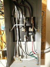
My home has a 400A service with two main panels:
  1. Left panel: Heavy loads, always on grid power
  2. Right panel: Household loads, fed by a manual transfer switch
    • Transfer Switch Up position: Grid power on right main panel
    • Transfer Switch Down position: Inverter power (solar/battery) to right main panel
Goal: Keep the left panel on grid power for heavy loads, and transition the right panel to run exclusively on solar/battery.

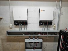
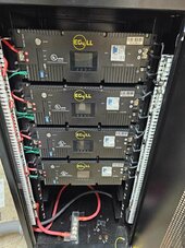
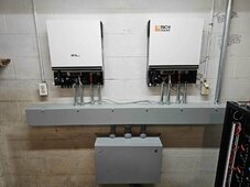
I'm running two LV6548 inverters in split phase, so far I have 4 of the EG4 48v 5kw batteries, I plan to expand that up to 6 batteries over time.

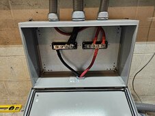
I've finished the battery and inverter setup, and it works great. Now I need to get the mount and solar panels up (14, 390w panels). Here's some progress pics, feel free to critique or point out changes/safety issues!

Special thanks to @timselectric and @ricardocello for answering many questions in DMs
447883505_983235119695666_5602154808423453436_n.jpg445951397_797818659119625_2575346708028083402_n.jpg442443930_1007356557640336_2057058642737681868_n.jpg441897883_3605048709711684_2634806408550570799_n (1).jpg436242487_394785160201401_6334237769835951584_n.jpg441987809_1447744785849943_7005870180982992260_n.jpg
 
My home has a 400A service with two main panels:
  1. Left panel: Heavy loads, always on grid power
  2. Right panel: Household loads, fed by a manual transfer switch
    • Transfer Switch Up position: Grid power on right main panel
    • Transfer Switch Down position: Inverter power (solar/battery) to right main panel
Goal: Keep the left panel on grid power for heavy loads, and transition the right panel to run exclusively on solar/battery.

I'm running two LV6548 inverters in split phase, so far I have 4 of the EG4 48v 5kw batteries, I plan to expand that up to 6 batteries over time.

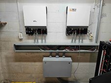
I've finished the battery and inverter setup, and it works great. Now I need to get the mount and solar panels up (14, 390w panels). Here's some progress pics, feel free to critique or point out changes/safety issues!

Special thanks to @timselectric and @ricardocello for answering many questions in DMs
View attachment 220467View attachment 220466View attachment 220471View attachment 220464View attachment 220463View attachment 220468
Looks good.

Why do you want to keep the larger panel on Grid?

Just $$ or space or some other logistical issue?
 
Looks good.

Why do you want to keep the larger panel on Grid?

Just $$ or space or some other logistical issue?

The on-grid panel only has breakers over 30A in it, so stove and both AC units, water heater, etc. The other panel ran off the inverter has everything else in the house.

I don't think I have enough amperage output across both phases between my two LV6548 inverters. It comes out to about 55 amps on each phase, which wouldn't be enough to run everything. I hope to upgrade my inverters in the future as $$ allows, but I wanted to get my feet wet and still get some cost savings/backup power at the same time :)
 
Looks like cables from battery are slightly smaller than each of the two cables to inverters. But sized large enough for both?

We put plastic nuts on ends of metal conduit. Are those supposed to be used for plastic conduit nipples too?

Each battery has its BMS. Is there fuse or breaker between batteries and inverters?
Inverters may have breakers - mine have that on Batt+ only.

Fuses for catastrophic shorts before the inverter? In case BMS doesn't survive and can't interrupt current.

Maybe fuses for individual batteries are useful, not sure. Because I'm not sure they would blow even if one battery started getting backfed by the others. You do have individual batteries with BMS, which is good (parallel strings of cells without FET or contactor would be a problem.)

Some MPPT can fail and apply PV Voc to BMS, causing it to fail. Some models are isolated so failsafe.
This AIO with DC/DC converter between 48V battery and HV DC rail I think would have an isolated converter so should be safe, but I'm not certain of the design. Perhaps someone familiar can confirm.

PV not connected yet. I just see MC4 connectors on bottom of inverter, which would likely get wired with just PV extension cables.
Run a ground wire to PV frames too! People have been getting shock from coupled AC when they don't!
 
Looks like cables from battery are slightly smaller than each of the two cables to inverters. But sized large enough for both?
Appreciate the insight!

The cables are 4/0 copper for the entire run, 4/0 off battery bank, and 4/0 to the inverters as well, for both positive and negative.

There's a 350A Class T fuse right off the positive busbar from the batteries (pictured on the floor of the battery rack). Hopefully that, plus the BMS and breakers on each individual battery is enough.

Yes no PV yet, need to do some digging and concrete work for my mounting.

Could you please elaborate on the last sentence about the ground wire to PV frame? I'm not really sure how to ground the solar array/frame. It all links back to the main ground rod for the house off the main panel. If I added a second ground rod for the solar array chassis, I wasn't sure if that would create a ground loop.

Nice! looks good. Is that battery rack top heavy?

It's a bit top heavy but surprisingly sturdy, the server rack is very well built. I will add two more batteries in at the bottom as soon as I have the cash to do so, and that should balance it out.
 
I don't worry about "loops", mostly that refers to an issue for analog or factory floor communications.

These AIO tend to drive common mode AC onto PV+/-, and there is capacitance from PV cells to PV panel frames.
If you just connect PV wires, when you're standing on the ground and touch the frames, you're likely to get a low-current shock.
If a fault develops in the panel and moisture etc. carries current from PV circuit to frames, you could receive a dangerous high voltage DC shock.

The inverter chassis should have ground wires back to any breaker panel feeding its input and grid or generator source. Also ground wire to loads panels. The ground wire goes though same conduit/cable as L1/L2/N. There is a N-G bond somewhere, only one place.

Similarly, all PV panel frames should be bonded together, either a wire going through lugs or a listed method to bond to mounting rails (some clamps, WEEB washers, etc.), and a wire must run from the panel frames or rails back with the PV wires to the inverter chassis.

The PV array can't just be grounded to a separate ground rod, with no metal conductor back to the rest of the system.
It also shouldn't be bonded with a ground wire that takes a path different from PV wires, for instance going to house ground rod or AC breaker panel. It should go together with PV wires, bond to inverter chassis, and ground wire for AC circuit also bonds to inverter chassis.
 
very similar setup to what I have.

2 LV6548 (the old 250v type)
6 eg4 batteries
12kw PV panels for the off grid system

the meter is 400 A, power to two 200a fused disconnects, then one goes to the house grid 200a panel, and the other to a 200a grid panel on the workshop.

the workshop grid panel also provides the 60a AC input for the lv6548 inverters

also each 200a main grid panel has its own gridtie system. 6.4kw on the house grid panel and 7.1 kw on the workshop grid panel

23kw solar all together

the entire house is run from the 60a off grid system except for the hot water and the electric dryer.

you are going to love your setup. my electric bills average about $25/ month and 10 of that is a base fee
 
The on-grid panel only has breakers over 30A in it, so stove and both AC units, water heater, etc. The other panel ran off the inverter has everything else in the house.

I don't think I have enough amperage output across both phases between my two LV6548 inverters. It comes out to about 55 amps on each phase, which wouldn't be enough to run everything. I hope to upgrade my inverters in the future as $$ allows, but I wanted to get my feet wet and still get some cost savings/backup power at the same time :)
Makes sense.

Not sure how many of those units you can parallel but if you get enough just put in 400 amp SER transfer switch one side Grid one side Solar like you have it.

Any issue you just pop back over to grid and shut down solar side.
 

diy solar

diy solar
Back
Top