diy solar

diy solar

Looping two panels from inverter

Jim1033

New Member
Joined
Jan 27, 2021
Messages
92
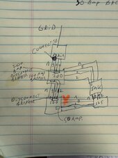
Ok, this is a little odd and maybe even not so smart, but want to be sure. I will try to be clear. see picture sorry for bad hand writing. I should start with the house panels. I have 400 amp service. One line goes to the main house 200 amp panel and the other is not important to this. There is a 200 amp disconnect breaker built in to the second panel. There is a 100 amp line to another panel. There is also a 200 amp disconnect breaker on that panel. I have the 200 amp panel feeing to my inverter with a 30 amp breaker. I use a pigtail to plug into the inverter. The inverter feeds another small 135 amp panel. There are 2 x 30 amp breakers. One breaker goes to the 100 amp panel with a 30 amp breaker back feeding to it. The intent was in an emergency I could run lights, fans fridge. Essentially an emergency feed panel from the inverter. I would just isolate it from the 200 amp panel and be good to go. I can and have in an extended situation isolated the 200 amp panel from the main / grid and ran some other minor items from the 200 amp panel from the 100 amp panel. So essentially back feeding from the 100 to the 200 amp panel. So to the question. I can technically back feed both panels with 2 separate 30 amp breakers. Doing so independently is no problem. But could I feed both panels and leave the breaker closed between them. Effectively looping the 2 x 30 amp lines for hopefully 60 amp combined. Or will there potentially be a phase issue with 2 lines not the same length. Yes I know I need to get the phases correct in each panels. But could I have an issue. They are probably within 10’ to 20’ of being the same length lines to them. Eventually I will have the solark 15k just runs everything like it should. It would go between the main and the 200 amp panel. Then there should be no issues. It just may take a little while to get that done. Thanks for any input. IMG_2160.jpegIMG_2160.jpeg
 
Hhhmmmm… I am not sure if the question was that unclear or if it is not an easy answer. At this point I think I just need to get it in right. I am also having an issue with the arc fault circuits. When I isolated from the main and the arc-faults are not working at least some of them. I want to connect the ground and neutral at the Sol-Ark but don’t want to mess anything up either. I need to look at it closer.
 
Hi Jim,
You may have to break that question down a bit. Basically ask it in smaller parts.

Lot's of smart people here, but that is a very big combo question!
 
Short answer is no.
That would be a parallel feeder.
Minimum conductor size for a parallel feeder is 1/0 AWG.
And the parallel conductors must be the same length.
And protected by a single OCP device. (Breaker or fuse)
 
I figured…thanks. I also think I found my other answer on the neutral ground question.. (no, it would potentially be a shock hazard… ) but what confuses me is I am pretty sure that the ground and neutral make it back to the main panel separately. So why would the arc fault breaker just not work when the solark is running them. I mean will not trip, reset or work to connect power. And it was not just one… also the only other thing is I guess the neutral and ground loop through 2 sets of wires. (Parallel each one separate at least to the first sub-panel) I thought I saw something about a setting if you have arc fault issues. Not sure where and also if it would actually take care of it. Anyone else have this issue. I guess I should look harder.. another thing currently I have no solar on this setup. I am not talking arc fault from solar. I see that a lot in the posts.
 
Last edited:
I am also having an issue with the arc fault circuits. When I isolated from the main and the arc-faults are not working at least some of them. I want to connect the ground and neutral at the Sol-Ark but don’t want to mess anything up either. I need to look at it closer.
It depends on the type of "isolation" .
If the neutral is disconnected, then the existing N/G bond is lost. And must be replaced during isolation from the existing system.
If the neutral is not disconnected. The existing N/G bond is still the only one that should exist.

Make sure that all of the grounding is correct.
There should only be one grounding system for everything.
 
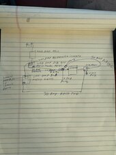
I do appreciate the help. So I did do a separate grounding rod to ground the inverter. The one on the chasis. It does not connect to anything else. I am hoping to have it set up correctly asap. I had an emergency set up with a 10k Chinese inverter. The odd thing is it was the same configuration but did not have issues. The only differences is the automatic disconnect on the solark 15k. (That I am aware of) l was doing it as a critical loads panel UPS so that the inverter only powered that panel. Pass through if there was grid power and battery if not. So question. If the ground and neutral go to another panel then to the main that has that connection. Can I break the connection to my bypass system. Each panel would still have a connection to the ground and neutral. There would be one wire that only had the power. I could even leave the ground and neutral connected in the wire but not connect it in the panel that has the other ground and neutral. One other correction I do isolate the 100 amp panel by the breaker between the 200 and 100 amp panels. See image. Again sorry for horrible hand writing. IMG_2172.jpeg
 
So I did do a separate grounding rod to ground the inverter. The one on the chasis. It does not connect to anything else.
This serves no purpose.
If it's not connected to the existing grounding system, it isn't grounded. (It's only earthed)


If the ground and neutral go to another panel then to the main that has that connection. Can I break the connection to my bypass system. Each panel would still have a connection to the ground and neutral.
I wouldn't.
This would only complicate the system.
If the N/G bond is lost. It must be re created, while it's disconnected. And the replacement must be disconnected, when you switch back to the main.
 
In the picture you have a "wiring circle". Which I am not fond of at all.
Wiring should be linear. A>B>C>D
When it circles back around, I cringe. Because it creates parallel paths.
Loops should be avoided.
Unless all current carrying conductors are switched. (Lines and neutrals)
 
This serves no purpose.
If it's not connected to the existing grounding system, it isn't grounded. (It's only earthed)


I wouldn't.
This would only complicate the system.
If the N/G bond is lost. It must be re created, while it's disconnected. And the replacement must be disconnected, when you switch back to the main.
Understand on the ground. The N/G is more complicated. It would not be lost. It is still there through the first 200 amp panel. The hots are only the only thing broken by the breaker. In fact the N/G would be looped as shown even thought line1 line2 would be broken by a breaker but the N/G is looped as shown.
 
In the picture you have a "wiring circle". Which I am not fond of at all.
Wiring should be linear. A>B>C>D
When it circles back around, I cringe. Because it creates parallel paths.
Loops should be avoided.
Unless all current carrying conductors are switched. (Lines and neutrals)
I also agree with this. I did forget to X the connection between the 200 amp and the 100 amp panel. So effectively the line is from the main to the 200 amp panel through the inverter to the 125 amp panel to the 100 amp panel. So the 100 amp panel acts like a critical loads panel through the inverter. Again sorry for the confusion. I still think there is something still off. I need to turn off everything then turn things on until I figure out what is causing the arc faults to mess up.
 
So update… will say user error on the arc fault issue. Accidentally put one of the load leads to gen and one to load. No power was getting to the side that I thought the arc faults was not working… I am mad at myself for not seeing it right a way. Was late the night I did it. Changed it and SolArk is now working perfect.
 

diy solar

diy solar
Back
Top