Ok when I choose min th it asks to connect to a network but when I choose sph it brings up the camera to scan the serial or enter it manually.
I think that's the problem @upsideup is having? It doesn't accept the serial number?
No bueno
Correct. Doesn't accept serial number at that point. Also, no Wifi networks are visible so even if it did not sure it would work?
Talking with self2solar. I am sure it will get figured out.
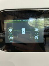
Cars are charged....Battery is almost charged... the house is not using much.....