diy solar

diy solar

Raising panels with gas struts

donb108

New Member
Joined
Dec 30, 2021
Messages
84
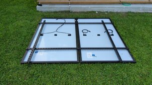
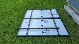
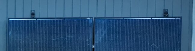
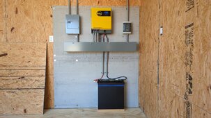
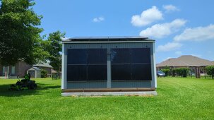
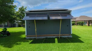
Still working on my shed project (off grid, EG4-3K, 8 panels). I have four panels on the roof and four on the back wall, all in a single string of 8, and facing south. The wall mounted panels tend to limit production of the entire string. Since the wall mounted panel assemblies are hinge mounted, I can lift them up with a 2x4, and production goes way up (900watts vs. 2400watts).

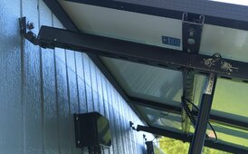
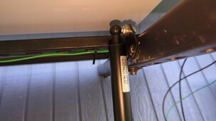
Lifting the panels with a 2x4 is difficult, so I'm trying to use gas-struts instead. I've tried three different sets of struts from Amazon and none are working quite right. The first set was way over powered; I couldn't lower the panels. The second set was weak and too short; they ran out of travel. The third set is better, but still not quite right.

Amazon has lots of struts, but the advertised ratings and mountings make it difficult to select the right ones. Using the calculator at gasspringsshop.com gives believable results, but their struts are way expensive ($400+); I replaced the gas struts on my car for $40. And, thier design results were a lot different from most others.

The linked video shows the panels rising up by themselves, but not all the way, I have to push them up a little. Putting them down needs a little more force than I was hoping for, and they don't stay down in-place. I probably have the mount points or something else wrong, but I'm not sure how to solve it. Any suggestions on what to try next?


Attachments

  • IMG_20240119_134002_247-a.jpg
    IMG_20240119_134002_247-a.jpg
    293.6 KB · Views: 22
  • IMG_20240525_122331_692-a.jpg
    IMG_20240525_122331_692-a.jpg
    325.6 KB · Views: 23
  • IMG_20240610_140457_176-a.jpg
    IMG_20240610_140457_176-a.jpg
    322.4 KB · Views: 23
Last edited:
I would suggest that you take a look at how a Santa Maria or Argentine grill raises and lowers the grill bed. You need to set up a cranking wheel with a counter weight to easily raise and lower the panels. Take a look at Marygrove awnings. They do exactly what you want to do.
 
Last edited:
I'm currently toying with a similar idea but using automatic gate linear actuators their rated for 750kg and atleast here in Asia aren't much difference in price compared to gas struts. Someone has done something similar in another thread though has had to compensate with more design from buying cheaper actuators.
 
I'm currently toying with a similar idea but using automatic gate linear actuators their rated for 750kg and atleast here in Asia aren't much difference in price compared to gas struts. Someone has done something similar in another thread though has had to compensate with more design from buying cheaper actuators.
Look for a linear actuator like the kind used to raise and lower satellite dishes. They will be like 16-24 inches and very great lifting capacity. and cheap. wire it up and have at it. From amazon.com:

ECO-WORTHY Heavy Duty 330lbs Solar Tracker Linear Actuator Multi-Function (12V, 12")
 
Santa Maria or Argentine grill raises and lowers the grill bed
Hmm, interesting, but I'm not sure how to apply those to panels.

using automatic gate linear actuators
Linear actuators are pretty interesting, but I'm left with the same questions (actuator length/travel/force/mounting points). I've only found one LA online calculator, but applying it to solar panels is a bit confusing. They seem to be big on hatches.

The Amazon support guy recommends using their 44" strut and gasspringsshop.com recommends 41.26". I bought the 44" from Amazon, hoping it's close enough.

Most of the guidelines I've seen recommend the upper mount point to be 20-30% of the panel length. My range works out to 14.4"-21.6", and I have it mounted at 18.5". However, gasspringsshop.com calculates 11.81"; I'm guessing my mount point should be shorter.

Once the upper mount point and the max opening angle is selected, the lower mount point is whatever it is.

I'm tempted to change the upper mount inward just to see what happens.
 
Hmm, interesting, but I'm not sure how to apply those to panels.


Linear actuators are pretty interesting, but I'm left with the same questions (actuator length/travel/force/mounting points). I've only found one LA online calculator, but applying it to solar panels is a bit confusing. They seem to be big on hatches.

The Amazon support guy recommends using their 44" strut and gasspringsshop.com recommends 41.26". I bought the 44" from Amazon, hoping it's close enough.

Most of the guidelines I've seen recommend the upper mount point to be 20-30% of the panel length. My range works out to 14.4"-21.6", and I have it mounted at 18.5". However, gasspringsshop.com calculates 11.81"; I'm guessing my mount point should be shorter.

Once the upper mount point and the max opening angle is selected, the lower mount point is whatever it is.

I'm tempted to change the upper mount inward just to see what happens.
Sorry no idea how to explain it mathematically I'm more hands on I'd likely just take my measurements cut a stick to length at what the gas strut should be compressed and treat it like a puzzle physically moving it till I got the right angles and mount points.
 
Each linear actuator will have the following information:
length fully closed
length fully open
max force
voltage (I have seen 12v 24v 120vAC)

your PV panels will have varying load to lift them, ie while they are hanging vertical it will take very little force to begin lifting the lower hanging edge.
But as you lift and the angle changes, the load required to lift the array edge will increase. Your maximum will occur at the point the panel array are closest to horizontal (or the max angle).

To search for a linear actuator that will suitably lift the panels, you can measure the lift force with a fish-scale (or two together) attached to the edge where the actuator would be connected, and hold the scale at the correct angle that would match your LA angle. Now you know the force required, and it is best to use a LA that is at least 20% more than this value.
Closed and open lengths can now be determined by cutting a few pieces of wood, and playing with attachment points on the building - the attachment point on your array was already determined by where you tested the scale load to lift the array edge. Now you want to determine the building wall attachment point.

Generally the LA fully extended length will be the closed length x2 - 150mm (6 inches) or similar. So if you know the fully extended length you want is say 60 inches, then the closed length of a LA that can extend to 60-inches will be about 36-inches. You can confirm the lengths when you go searching for an actuator to suit the lengths and force you have calculated.
Cut two pieces of wood these lengths and play with where the attachment point could be on the building that will allow the movement you want. The LA may be set so in the fully down position the actuator is nearly parallel to the wall. This will be ok since the force required to move the array while it is hanging nearly vertical is very low, but inceases as the PV moves and changes angle adding more load (due to gravity) as it moves.
 
Gas struts are very interesting things to play with.

I built my own home brew 5Kw Warpverter into a modified two drawer filing cabinet, and arranged it so the whole hinged "guts" can be opened up to make it very easy to work on or to repair.
It took several attempts to get the gas struts to work properly so that the inverter chassis would stay in either the up or down position, requiring minimal effort to move it either way.

The trick is to move both the mounting points around to get the desired effect. By changing angles and leverage its possible to adjust the force at different strut angles to behave exactly as required. I think it would be very difficult to work out mathematically, but fabricating something out of wood and experimenting with it, its not difficult to get the required stroke and force to do the job.

I ended up buying three pairs of struts to finally get things exactly right.
Once it was working, I made up some proper strong mounting points from metal using the usual ball joints at each end of the strut.
All jolly good fun and quite instructive.

Once you have that working to support most of the load, it should be possible to add a much lower powered linear actuator to that (if required).

Here are some old pictures of my inverter.
Second and third pictures show the gas struts. Mounting points are quite critical.
 

Attachments

  • 2018-10-10_0002.jpg
    2018-10-10_0002.jpg
    238.1 KB · Views: 13
  • 2018-10-10_0004.jpg
    2018-10-10_0004.jpg
    296.1 KB · Views: 12
  • 2018-10-10_0001.jpg
    2018-10-10_0001.jpg
    305.8 KB · Views: 12
Here is an example of a pair of linear actuators - these are controlling the tilt on a group of PV panels on a West facing roof, the panels face South. (the trees in the background are East of the PV, separating my property from my neighbour, and blocking my early morning solar until about 10:00AM)
I wanted the fully extended length to give me a 72-degree angle for Winter, and the fully retracted length to give me 35-degree angle for Summer. The LA can also be positioned anywhere in-between if desired. Two LA position a rack of three JA 550 PV and two sets spaced far enough apart to prevent Dec 21st shading make up a set of six panels for a single string of 2s3p. The four LA cost me $300 USD delivered IIRC.
If I recall correctly, the lifting force is a function of the speed, the slower the actuator operates, the higher the load it will be able to provide.
(yeah, I really need to tidy up the wiring before the snow flies again...one thing at a time...
IMG_5518.jpg
 
Last edited:
To search for a linear actuator that will suitably lift the panels, you can measure the lift force with a fish-scale (or two together) attached to the edge where the actuator would be connected, and hold the scale at the correct angle that would match your LA angle. Now you know the force required, and it is best to use a LA that is at least 20% more than this value.
I found a see-saw calculator to get the balance point and force needed. Assuming I attached the LA between the fulcrum and the shed (similar to the gas-strut mounts), would this be a valid approach to determine the force?


Total load = 136 pounds
X = distance from the hinge to the upper attachment point (fulcrum) = 14"
L = distance from the upper attachment point (fulcrum) to the bottom of the panel = 58"

Calculating with the panels at horizontal, the needed force is 563.43 pounds. Using two actuators, Force = 282 pounds. I checked Windy Nation; a LA with that much force is kinda pricey, but way more than I need;


More shopping required.
 

Attachments

  • ScreenCapture_02 Jun. 24 12.56.gif
    ScreenCapture_02 Jun. 24 12.56.gif
    18.9 KB · Views: 4
Try to take a look at linear actuators for satellite dishes. Years ago I move a 300 lb 12 foot Paraclipse satellite dish with a 24 inch linear actuator about 170 degrees. You just have to see how these are mounted to understand where to mount the actuator and connect the arm to the panel structure. The screw on these in combination with a geared winch like motor make them very strong.

Actually, now that I think about it, why not just get a Harbor Freight or Amazon or your local powersports shop ATV winch (12V DC) and connect it up to raise and low the panels. This is cheap and easy and they have a remote control on them to be safe.
 
Instead of fixing the panels at the bottom edge like you are thinking build a rigid frame to hold the panels and attach it in the middle verse the bottom edge. Fix it so the panels are near the balance point and your actuator only needs to be capable of a few pounds. Then you only need long travel, but not as much as with the panels flat and fixed at the ends.

This would also raise the panels above the mounting surface and allow more cooling air under them.

If a center attachment isn't practical you could hang a weight along the bottom edge.
 
I found a see-saw calculator to get the balance point and force needed. Assuming I attached the LA between the fulcrum and the shed (similar to the gas-strut mounts), would this be a valid approach to determine the force?
Probably not.
That seesaw formula assumes all the forces are vertical, and remain vertical.
With a gas strut, both the length of the strut, and all the angles change considerably throughout the stroke, and that really complicates things.

The weight of the panels acting on the strut changes too.
Maximum with a horizontal panel, zero with the panel vertical (either up or down).

If you have more than one panel to move, gas struts will cost a lot less than a powered actuator on each panel.

Simplest way might be to make a full scale working model out of wood, using a small barbell weight attached to the middle of a plank (the centre of gravity) instead of an actual panel.

You can then drill holes all over the place and really experiment with different strut mounting locations for BOTH ends of the strut.
Use half the actual real panel weight, and then only one strut will be needed for this testing.
A flat plank pivoted with a bolt to a sheet of MDF or plywood will give you a flat two dimensional working model for a single strut.

It should work like the hatch on a hatchback vehicle. The strut balances out the weight, so it takes very little effort to move, and will stay pretty much in either the up or down position or anywhere in between by itself.
 
I don't mind the thinking part, but it is turning into more of a project than I had imagined. I'm also working on a couple of other projects that kinda took over for a while. I'm slowly moving stuff into this new shed and finding that most of the small gas engines that have been sitting around for two years need attention (generators and mowers that won't start). I rebuilt three carburetors this week.

Anyway, the panels are assembled on a Uni-strut framework that was fairly difficult to mount, so I can't easily take them down; any adjustments have to be with them in place. To move a mount point, I have to drill new holes in the unistrut and the shed. Not impossible, but takes some time ; and I'd like to minimize the number of holes in the shed.

I'm pretty sure either gas-struts or linear actuators would work, but it might take a fair amount of experimenting to get it right. I originally posted this thread because I was looking for a simple solution without spending a ton. Hmm; good, fast, cheap...pick any two.

I have all the hardware to move the mounts of the gas-struts, so I'll probably give that another try. But not right away, I have a trip coming up, so it will be a while :)
 

Attachments

  • IMG_20240504_163632_573-a.jpg
    IMG_20240504_163632_573-a.jpg
    382.6 KB · Views: 6
  • IMG_20240504_163710_766-a.jpg
    IMG_20240504_163710_766-a.jpg
    389.5 KB · Views: 6
  • IMG_20240424_164613_317-a.jpg
    IMG_20240424_164613_317-a.jpg
    54.4 KB · Views: 6
  • IMG_20240620_181649_959-a.jpg
    IMG_20240620_181649_959-a.jpg
    259.7 KB · Views: 6
  • IMG_20240620_181730_988-a.jpg
    IMG_20240620_181730_988-a.jpg
    102.1 KB · Views: 6
Anyway, the panels are assembled on a Uni-strut framework that was fairly difficult to mount, so I can't easily take them down; any adjustments have to be with them in place. To move a mount point, I have to drill new holes in the unistrut and the shed. Not impossible, but takes some time ; and I'd like to minimize the number of holes in the shed.

I'm pretty sure either gas-struts or linear actuators would work, but it might take a fair amount of experimenting to get it right. :)
That is exactly why building a wooden scale model is the only practical pain free way to go about a project like this.
You can bodge something up at ground level, drill holes all over the place to get it working correctly in wood, and try alternative gas struts and do it all in a convenient place to work.

All you really need to know is the total final weight of the panels plus frame, which you can probably measure in situ with a supporting pole set at the centre of gravity, and some bathroom scales (with the panels set horizontal). Then divide that weight by the number of struts you plan to use.
It does not matter if the scales are inaccurate. If you are using three struts, just fit a suitable weight to your working model that reads one third of whatever the scales tell you, and you will be sweet.

What I did with my filing cabinet was cut two pieces of plywood that fitted snugly inside the metalwork. That gave me a flat surface into which I could drill holes at any location I wanted. By some miracle, the lower mounting points ended up very close to the where the original filing cabinet slides fitted. Once I knew where the top holes needed to go I bought suitable heavy duty right angle brackets from a hardware store that had a metal brace in the right location.
I drilled three holes an inch apart in the upper hinged part, so I could do some fine tuning later, although the original anticipated hole locations worked out perfectly.

Its all trial and error, but once you get set up, it becomes a really interesting exercise and it does not take very long to go from hopelessly wrong, to being very precisely balanced. Once the gas struts take all the load, the actuator can be quite light duty, and you probably only need one actuator.
 
Last edited:
I used a short piece of channel steel bolted into the main strut with the typical spring-nuts for the connection points of the linear actuators - so just loosening the bolts allows me to slide the short piece up or down the strut to try out different locations, without drilling any holes. I used strut at both ends of the LA so both points are adjustable.
The old-man used to say "if ya can't make it accurate, then at least make it adjustable" so true ;)
 

diy solar

diy solar
Back
Top