diy solar

diy solar

Large panel rooftop single axis solar tracker - working

Murphyslaww

New Member
Joined
Dec 27, 2021
Messages
109
Location
Austin, TX
Been working through some issues, but I now seem to have a working, albeit too expensive, single-axis,linear actuator, Arduino controlled, panel lift.

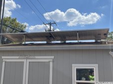
Once I have some materials sorted it’ll be likely, around $100/panel, and then around $70-100 for the tracker electronics, which will, for me, control all four panels as the motor driver has two outs and both panels on one eave of my shed will move together.

There will be at least another video when I move from a basic arduino nano to a IOT wifi version, where I’ll add the ability to move the panels via the Arduino cloud phone app, manually. The code needs some refinement as well.
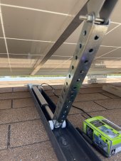
IMG_5846.JPG

Single Axis Solar Panel Tracker Arduino IOT powered!

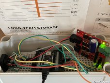
Added two youtube shorts of on in operation, one up, one down. I think I’m going to add a small ramp of wood similar to what is in the vid as the stop for it. I added the metal strapping to hold the actuator down as well. It’s working well. The initial self tapping bolts pulled out of the aluminum crossbar, so I added cap head bolts through it into the actuator pivot. I’ll be bringing the wiring and almost finished Arduino electronics inside the shed.


Last edited:
Interesting project.
not to poo poo anything, but only to draw attention to a potential issue: Wind uplift.
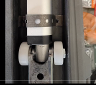
From your photo, the track does not have anything to prevent the wheels from lifting (ie if wind creates uplift force on the PV, the wheels just lift right up out of the track?)
Check it over and consider adding a pair of angles to the sides of those tracks that will stop the wheels from lifting up out of the channels.
 
Looking at your still photo, I was going to say wind could just flop the panel and lift the cylinder.
In video I saw plumber's tape holding the cylinder down.

1690725901809.png

I was thinking of rails over the top of rollers, as Off Grid said.

Plumber's tape may or may not be strong enough, but even if cylinder held securely, at full extension force from wind could bend shaft.


I don't see how your mechanism gets any lift when it is retracted to the point panel lies flat. If blocked at significant tilt, could work.
I used to have an F600 with dump bed, which could hold 11,000 lbs. The cylinder first rotated a cam which lifted bed partially, before cylinder worked directly at an angle to lift it.

You noted price. If your tilted panel casts a shadow beyond the shed it may capture additional light. To the extent it just casts a longer shadow on the roof, or would if panel and mechanism was located elsewhere on the roof, it doesn't produce more power than you would get by covering roof with panels (which are relatively cheap, especially used).

Is this a seasonal tilt, or tracking sun throughout the day? How many more Wh can it get vs. flat on roof?

Good project to study mechanisms and control.
 
I don't see how your mechanism gets any lift when it is retracted to the point panel lies flat. If blocked at significant tilt, could work.
From the still pic, the long bolt upper pivot may prevent the PV lift arm from dropping into the channel, so it is always at a small angle to the linear actuator alignment. Provided the actuator has sufficient force, it would be able to lift from lowest position. The more initial angle the easier the actuator can begin lifting.
Plumber's tape may or may not be strong enough, but even if cylinder held securely, at full extension force from wind could bend shaft
I assume the actuator is not designed for the bending moments especially as you say at full extension, which will also be when the PV creates the largest area exposed to the wind. Simple solution is to enclose the track above the wheels, so the wheels are trapped in a track, no bending forces on the actuator this way, and not relying on the plumbing strap. The support system relies on the track being well secured to the roof as well naturally.
 
Great job! I think with a little refinement of the wind issues mentioned this could work excellent on a van system where the amount of panels is at a premium. just think you can pull up somewhere press a button and your 2 panels can track the sun giving you max PV throughout the day.
 
From the still pic, the long bolt upper pivot may prevent the PV lift arm from dropping into the channel, so it is always at a small angle to the linear actuator alignment. Provided the actuator has sufficient force, it would be able to lift from lowest position. The more initial angle the easier the actuator can begin lifting.

Sufficient force - for a moment I was thinking that would push frame off glass. I see an aluminum rail in line with actuator, which for the most part would prevent that. I'd rather see a hinge connected to that rail, so bending of frame and tiny screws holding "picture frame" together don't have to resist the large off-angle force needed.
 
I've been think of tracking for a while myself. I'm not sure it will be cost effective compared to the gains in my system at least. It might be cheaper to add more panels instead of actuators. Of course, the spacing is limited on that shed so actuators may be the way to go.

Ignoring the IoT aspect, you could drive the trackers from a cheap op-amp and relay instead of a Nano for maybe 1/20 the cost.
 
All my panels tilt, for summer/winter using 30 degrees and 60 degrees approx.
I certainly thought about daily tilting, arduino driven, single axis. but this is not as simple as first appears.
From PV Watts daily tracking was not going to be worth the effort, even the seasonal tilt is only 9% difference for the year.
Adding panels is quite a bit easier, especially when you have a lot of area to work with.
If we didn't have snow for five months of the year, I admit I wouldn't bother with tilting.
 
For sure. I have an anemometer to apply. Forgot to mention it. A little more coding, as well. In the morning, through close to 11am, the west panels, get no sun, so I’ll be tilting them up 60 degrees or more, and I think that will be a significant improvement as they are obviously tited down, facing westward, and will move to tilted up, facing eastward.
Interesting project.
not to poo poo anything, but only to draw attention to a potential issue: Wind uplift.
From your photo, the track does not have anything to prevent the wheels from lifting (ie if wind creates uplift force on the PV, the wheels just lift right up out of the track?)
Check it over and consider adding a pair of angles to the sides of those tracks that will stop the wheels from lifting up out of the channels.
 
Last edited:
Looking at your still photo, I was going to say wind could just flop the panel and lift the cylinder.
In video I saw plumber's tape holding the cylinder down.

View attachment 160149

I was thinking of rails over the top of rollers, as Off Grid said.

Plumber's tape may or may not be strong enough, but even if cylinder held securely, at full extension force from wind could bend shaft.


I don't see how your mechanism gets any lift when it is retracted to the point panel lies flat. If blocked at significant tilt, could work.

Is this a seasonal tilt, or tracking sun throughout the day? How many more Wh can it get vs. flat on roof?
You are exactly right on the lift. It has to start from an angle and it has to be significant. On the right side system, the silver bar is 16”, and it was torquing the mounts and hinges, before the lifting started, but they are flimsy. I shortened the left side to 14” and it works much better, but still needs to be above a negative angle, as you might expect. I have to give up a little beneficial angle on the east side, but it won’t matter when I move to the west side. I can start that side with a larger angle, as I’m going to want that to start the day at 60 degrees plus.
 
Last edited:
Sufficient force - for a moment I was thinking that would push frame off glass. I see an aluminum rail in line with actuator, which for the most part would prevent that. I'd rather see a hinge connected to that rail, so bending of frame and tiny screws holding "picture frame" together don't have to resist the large off-angle force needed.
It becomes immediately apparent that these panel frames are not made for this, so yes, I have added the 1” square crossbar, which is actually what the actuator attaches to. There is also a 20” piece of L aluminum stiffening up the front of the panel frame.
 
Sufficient force - for a moment I was thinking that would push frame off glass. I see an aluminum rail in line with actuator, which for the most part would prevent that. I'd rather see a hinge connected to that rail, so bending of frame and tiny screws holding "picture frame" together don't have to resist the large off-angle force needed.
Added some youtube shorts of it in operation to the first post.
 
I did a swap to Victron Controller, Cerbo GX, and added a smartshunt. We're testing all of this for a future move to a central america, off-grid location in the near future. There have been some people that have reported a significant difference in the Victron's output vs. the Epever.

This allowed lazy me to do some testing. In full sun days with no actual tracking, only the east side done and just moving the panels from lowered, to full extension, mid-day, I gained about 530 watts. About 9%. I’ll eventually add the actuators to the other side, where I think there is likely more to be gained. I’d guess I’ll get to 20%. The resoldering of the tracker is almost done, so it should be tracking soon. We’ll see if actually following increases production vs the mid day move.
 
Last edited:
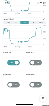
Coding for the Arduino Cloud controller up and working. I can now move the panels up and down from the Arduino remote phone app. Have it moving up by sensor data from LDR's, and back down at night. I'll be reinforcing the hinges this weekend, and start building the lifts for the other side. Looks like without really shopping for deals, This is in the $350-400 range to lift 4 panels, just to show the economic folly of this endeavor. That is more than a $400 watt panel brand new, and right around what I paid for all 4, used, 300 watt panels. I might be able to increase my output by between 1 to 1.5kw per full sun day. 1.5kw would be around a 25% increase. Even if everyday was a full sun day, that would be around only $71 return per year at our current rates. Ya gotta want to save the world, or just like to geek out. The actuators are being powered by a bench power supply right now, and run at about 2amps, or 21ish watts for about a second at a time. The actuators travel 10mm/second. I moved up to a more powerful Drok motor controller as the initial lift amperage requirement was a little too much for the generic controller which I think tops out at 2amps per channel. I think these wanted like 2.5 amps per channel at start. The control electronics were only around $30. I'd bet one could get the cost down to $200 if you bought online metal. I just picked all mine up at Home Depot.

I'll be producing another video this weekend on it, along with a comparison test I'm doing this weekend in the shed with swapping out the new Victron back to the Epever for a day, and then to a cheap PWM charge controller for the next day. Curious to see what those results look like.


IMG_6665.JPGIMG_6666.JPG
IMG_6673.PNGIMG_6731.PNG
 
Last edited:
Got a link for those actuators?

They, for whatever reason, are not available in the 12" size. Just about every other size, though. I've been running two of them to open my tool shed roof for about a year, which has two 50lb panels on it, and needs to be lifted about a foot to get past the negative angle, so the hydraulic struts help enough for my S/O to lift it. They seem well built.
 
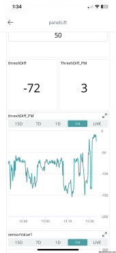
As coded, the system seems to be working well. I get a wierd panel lift at night occasionally.

My code is not commented yet, so forgive me, and remember this is with the arduino cloud code, so you'd also have a thingProperties.h file and a secrets file... this is not the final. I'll likely build a hackster.io project with the final code. I'm not using the variable int threshDiff; as I'm not allowing the panel to come down during the day, only go up. I don't see a need for it to do so, and clouds confuse it, and you get movement with no benefit.

C++:
/*
  Sketch generated by the Arduino IoT Cloud Thing "Untitled"


  Arduino IoT Cloud Variables description


  The following variables are automatically generated and updated when changes are made to the Thing


  int sensorValue1;
  int sensorValue2;
  int threshDiff;
  int threshDiff_PM;
  int threshold;
  bool panel_Down;
  bool panel_Stop;
  bool panel_Up;
  bool useSensor;


  Variables which are marked as READ/WRITE in the Cloud Thing will also have functions
  which are called when their values are changed from the Dashboard.
  These functions are generated with the Thing and added at the end of this sketch.
*/


#include "thingProperties.h"
const int Extend = 6;
const int Retract = 7;


int sensorPin1 = A1;
int sensorPin2 = A2;
int counter = 0;
int numAverage = 10;


void setup() {
  // Initialize serial and wait for port to open:
  Serial.begin(9600);
  // This delay gives the chance to wait for a Serial Monitor without blocking if none is found
  delay(1500);


  // Defined in thingProperties.h
  initProperties();


  // Connect to Arduino IoT Cloud
  ArduinoCloud.begin(ArduinoIoTPreferredConnection);
 
  /*
     The following function allows you to obtain more information
     related to the state of network and IoT Cloud connection and errors
     the higher number the more granular information you’ll get.
     The default is 0 (only errors).
     Maximum is 4
 */
  setDebugMessageLevel(2);
  ArduinoCloud.printDebugInfo();
}


void loop() {
  ArduinoCloud.update();
 
  if (useSensor) {
    for (counter = 0; counter < numAverage; counter++) {
      sensorValue1 = analogRead(sensorPin1);
      sensorValue2 = analogRead(sensorPin2);
      threshDiff = (sensorValue1 - (sensorValue2 + threshold));
      threshDiff_PM = (sensorValue2 - (sensorValue1 + threshold));

    }


    if (sensorValue2 > sensorValue1 + threshold)
    {
      digitalWrite(Extend, HIGH);
      digitalWrite(Retract, LOW);
      delay(1000);
      digitalWrite(Retract, LOW);
      digitalWrite(Extend, LOW);
      delay(500);
    }
    else if ((sensorValue2 + sensorValue1) < 300)
    {
      digitalWrite(Retract, HIGH);
      digitalWrite(Extend, LOW);
      delay(500);
    }
  }
 
  // If useSensor is false, read the button state and turn on/off the actuator based on it
  else {
    if(panel_Up == HIGH) {
      digitalWrite(Extend, HIGH);
      digitalWrite(Retract, LOW);
    }
    else if(panel_Down == HIGH) {
      digitalWrite(Extend, LOW);
      digitalWrite(Retract, HIGH);
    }
    else if(panel_Stop == HIGH) {
      digitalWrite(Extend, LOW);
      digitalWrite(Retract, LOW);
    }
    
  }

  Serial.print("sens_1 ");
  Serial.print(analogRead(sensorPin1));
  Serial.println();
  Serial.print("sens_2 ");
  Serial.print(analogRead(sensorPin2));
  Serial.println();
  Serial.print("Threshold Difference ");
  Serial.print(threshDiff);
  Serial.println();
  delay(1000);

}

/*
  Since Threshold is READ_WRITE variable, onThresholdChange() is
  executed every time a new value is received from IoT Cloud.
*/
void onThresholdChange()  {
  // Add your code here to act upon Threshold change
}


/*
  Since UseSensor is READ_WRITE variable, onUseSensorChange() is
  executed every time a new value is received from IoT Cloud.
*/
void onUseSensorChange()  {
  // Add your code here to act upon UseSensor change
}


/*
  Since PanelUp is READ_WRITE variable, onPanelUpChange() is
  executed every time a new value is received from IoT Cloud.
*/
void onPanelUpChange()  {
  // Add your code here to act upon PanelUp change
}


/*
  Since PanelDown is READ_WRITE variable, onPanelDownChange() is
  executed every time a new value is received from IoT Cloud.
*/
void onPanelDownChange()  {
  // Add your code here to act upon PanelDown change
}


/*
  Since PanelStop is READ_WRITE variable, onPanelStopChange() is
  executed every time a new value is received from IoT Cloud.
*/
void onPanelStopChange()  {
  // Add your code here to act upon PanelStop change
}
 
Last edited:
Back
Top