diy solar

diy solar

Renogy 500A Battery Monitor doesn't display alternator charging

kyzer1111

New Member
Joined
Jun 21, 2024
Messages
7
Location
Australia
Hello, I've seen a few threads discussing the Renogy Battery monitor not displaying correctly but mine appears to be a slightly different fault.

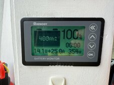
It correctly displays the discharge loads, it also displays charging from the solar panels. However it doesn't seem to take into account any alternator charging, therefore over time it thinks the battery is just constantly reducing. When I check on the charge controller it tells me the battery goes up to 100% once I've ran the van for a little while. Currently having to manually set it back to full when I know the batteries are fully charged. I've done the standard checks and the inverter, batteries and charge controller all appear to be working correctly, which brings me to the battery monitor display.

Any help would be immensely appreciated! Thank you in advance.

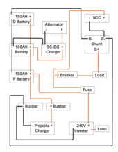
Current set up: 2x Solar panels, Renogy: 40A MPPT Charge controller, Renogy: Battery Monitor, Renogy 60A DC-DC Battery Charger, 1x 100ah Battery, 2x 150ah Battery.
 
The charge controller 100% is a meaningless number.

Does the alternator charging occur through the chassis?

If your battery is bonded to the chassis, your bonding wire needs to be on the SYSTEM side of the shunt, not the battery side of the shunt.

ALL loads and charges need to be connected at the SYSTEM side of the shunt, not the battery side, i.e., the ONLY thing connected to the battery (-) is the shunt.
 
The DC-DC Battery Charger is wried into the alternator, not sure if it's bonded through the chassis.

Just trying to whip up a certain diagram but in doing so I found that the B- on the shunt was connected to the same battery as the + on the SCC. Think it has maybe just been taking a reading from a single battery rather than the 3 of them in parallel.

I've now changed the B- side of the shunt to the end battery so the reading will be taken across all 3 batteries. Going to use up some power and see how it reacts when I start the engine. I'll try and get the circuit diagram uploaded shortly.

Thanks for the reply.
 
This is my current set up. D battery stands for Driver side, P for Passenger. The projecta charger is a plug in to mains inverter to charge the batteries up.

I reconnected the B- shunt negative cable from the P-Battery now onto the D Battery.

The battery monitor still doesn't indicate charging when the engine is running though.
Van Circuit Diagram .png
 
All charger negatives connect to the negative buss bar, or P-, not the battery. The alternator charger is negative connected to chassis/ frame/vehicle metal, connect bussbar negative to a suitable metal point.
Are you sure the diagram is correct ? Would expect the inverter and SCC positive to connect to positive buss bar.Screenshot_20231018-170047_Chrome~2.jpg
 
Last edited:
Apologies I did in fact miss out a line from the Fuse to the battery. This links the SCC and the inverter to the positive bus bar.

Here's an updated version.

Is my DC-DC charger wired in correctly? Or should it be positive on the P battery and negative on the D battery? Or does it not make any difference and will charge just fine as is? Don't know why the monitor is picking up the PV charging but not the engine running. At the moment I'm just guessing what I've got left in the batteries when the engine hasn't been run, defeats the point of having the monitor in the first place.

Thanks again in advance for the help!
 

Attachments

  • Screenshot 2024-06-22 at 21.45.41.png
    Screenshot 2024-06-22 at 21.45.41.png
    94.9 KB · Views: 2
Last edited:
Thanks again in advance for the help!
ALL chargers negative connect to the negative buss, connect the negative from the DC to DC to the negative buss, not the battery.
These is a repeat of my sugestion in post #5.
The only connection to battery negative ( apart for other battery negatives in a parallel set up) is the connection to the shunt, as shown in my diagram in post #5.
For the shunt to record all current flowing, all chargers and loads, including the DC to DC, must be negative connected to the negative buss bar or shunt P-.
Mike this has worked! We're now indicating charging from the alternator! Or the solar panels are having a hell of day...

Thank you all so much, feel more confident going off-grid now without the risk of black out.

If you notice anything else wrong with this set up or ways to improve it then please suggest. It seems like the previous owner who fitted it botched it somewhat. There's a number of cables that are redundant so it wouldn't surprise me. Cheers again.
 

Attachments

  • Screenshot 2024-06-23 at 09.04.18.png
    Screenshot 2024-06-23 at 09.04.18.png
    98.5 KB · Views: 2
  • IMG_0818.JPG
    IMG_0818.JPG
    288.1 KB · Views: 2
This portion confuses me:


1719098233176.png


I would assume this is the (+) power cable for the shunt. I don't know why there's a "LOAD" there, or how it's somehow attached to the breaker. This should be attached to either the (+) bus bar or the (+) battery terminal.
 
This portion confuses me:


View attachment 223954


I would assume this is the (+) power cable for the shunt. I don't know why there's a "LOAD" there, or how it's somehow attached to the breaker. This should be attached to either the (+) bus bar or the (+) battery terminal.
I think that it was made this way so that when the electrics are in use it goes through the breaker, links via the back end of the fuse, then on to the battery. I agree it could me more efficient. Took me a little while to figure out how it was all linked up as I was starting from scratch with this system.

Does it make any difference which battery the DC-DC charger is connected to?

Just arrived in country a week ago so trying to do the best I can with a $20 tool kit 😂
 
The DC-DC should be connected to the bottom battery in the sketch. You want your main (-) at one end and your (+) at the opposite end with no connections between them besides the cables that connect the batteries in parallel.
 

diy solar

diy solar
Back
Top