diy solar

diy solar

JK BMS 2" LCD vs 4.3" Power

hb48

New Member
Joined
Nov 15, 2023
Messages
19
Location
USA
Hi,

If i understand correctly the JK BMS LCD plug is 6 pin. K- , K+ (used for switch function), GND, Serial A, Serial B, & VCC 12v

The 2" Display plugs in and gets power from the BMS via GND and VCC pin.

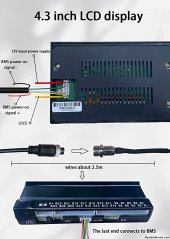
The 4.3" based on pictures appears not to use the same GND and VCC 12v itself and requires an external source? Why can't the BMS ground and power be used for the 4.3" LCD as well to keep the install simple and clean?

Also the cable harness I got does not look like the picture below. It does not have the red and yellow wire in those pins.
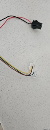
20231115_102046.jpg

4.3 Display Pinout.jpg

Thanks
 
Last edited:
Hi,

Can you confirm if this latest 4.3" LCD requires an external 12VDC or not? I just ordered all my hardware the past few days and now wondering if I need a 12V adapter.

Thanx!
 
Mine came with a wide input dc to dc converter that I had to install. I’m guessing 48-60v to 12v
 
I would think the BSM' LCD connector outputs the voltage of the battery (12, 24, 48). A converter would be needed only if the battery pack isn't a 12V one. Could that converter actually have a larger range ~20-60V? Pure speculation... when all my hardware has been delivered, at some point I'll get there and test it myself.

I'm still interested to learn if the LCD stays light up all the time when the BMS is on (not standby). If it doesn't stay on, I'll look at adding a status light that I can see from far and not have to walk to the unit.
 
After further examination.

The
new version 4.3 LCD screen has a single plug connector on the back. The opposite side of the board has a Micro memory card slot.

VCC for the news screen version is 12 to 36 volts. However if you are using the supplied connectors and plugging this into a new style JK BMS that is equipped with a (Display interface) the BMS will manage the required display power VCC for you.

The new version LCD also has a power switch supplied. This new system is easy plug and play…
I have 4 Battery systems, 3 are the new system. Now if I can just figure out how to connect the new LCD to my older BMS I won't need to buy another newer BMS...
 
Last edited:
My 4.3” displace had only one BMS connector to my 24v unit (2023), no external supply needed.
 
FWIW I got a new 4.3" display - only one back connector jst HY 2 8 pin. the cable has a red/blk PB for BMS start/off function, so only 4 wires go into the display 484 A,B and vcc +/-. NB the display has not auto/off on display as per the 2.4 display (which also has a convenient side start button. This is a troubling issue as its a big display you might not want it drawing ca 80ma 24/7. Looks like I will have to break one of the vcc lines and insert a toggle switch - Considering this cost ca £45 its a very Cheap Charlie result. IMHO this unit is not worth the extra over the cost of a 2.4" display £20. You get full data on BMS app free. But it does contain a 3m lead and a mini xlr plu/sock for use on your battery boxc. So thats worth having for mobile use. Im not sure how good the fuel gauge will be and more likely trust a coulomb meter for my golf cart app
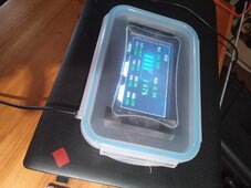
For outdoor use I will put it in a clear sandwich box with toggle switch. I doubt I will need the cell volt display in running use so touch screen is no use. If needed I can use my phone.

The PB long press shuts down the bms - so no power and needs a short press to restart (not so useful with Joe Public around?). I will have to wire/relay this into the cart key switch - no auto power off !!!!!!!!!! - go for small 2.4 meter.

fwiw data sheet
 
I can report that a toggle switch in the VCC line of the 4.3" jk display works as a power off sw, so no battery drain 80mA. It powers up in a few sec. The box is a well known for storage click-sealed moisture proof gasket PE type ca £1.5ea Ebay. They make good project boxes as its easy to cut holes and rectangles inwith a soldering iron - crude but it works. Doing this in conventional ABS is hard work and those boxes are ££. I needed fully weatherproof as it will sit outside on my GC. Note the small toggle switch on the side. I left the reset button inside as it should be rarely used and I can easily flip open the box if needed. Note I left the LED display inside showing through the box ok, rather than cut a hole as its not waterproof. I cant see me using the touch screen feature
 

Attachments

  • jk bms box.jpg
    jk bms box.jpg
    212 KB · Views: 4
Hit the EN button top right, unless you like guessing the text being displayed or English isn’t your native language.

Also for me it’s the instant read out of all cell voltages that I enjoy.
 
Hit the EN button top right, unless you like guessing the text being displayed or English isn’t your native language.
once you make your choice - its remembered
Also for me it’s the instant read out of all cell voltages that I enjoy.
For my GC cells volts are no interest to drivers no for normal use. Its all available on your phone. You only need to check say once/month during charging for a well adjusted system 99.9% of time IMHO YMMV
 
Everything is available via your phone so the display isn’t needed at all. . . .

Seeing I use the app to check cell balance, the display is a quick easy glance.
 
you cant be looking at your phone while piloting a GC, that why you have a dashboard display and you are only interested in fuel gauge. Cell volts are irrelevant hence no need to visit that display. So my screen can stay in its food box safe from the elements. YMMV
 
Can someone confirm that the BMS is outputting 12V on the screen connector? And if so, anyone know what JST connector type it is? I'd like to use that to power an ESP32 so I can directly connect that to the BMS and the RS485/CAN port without having to have a buck as well.
 

diy solar

diy solar
Back
Top