diy solar

diy solar

EG4 18kpv System Grounding

garybryan33

New Member
Joined
Aug 22, 2023
Messages
53
Location
California
This is for an off-grid system powering a garage. The system consists of 1 18kpv and 2 wall mount batteries.

1. The load panel is 70 feet from the inverter; I will be running 4awg, 2 feeds, and a neutral. Do I need to run a 4awg ground wire as well or could it be smaller?
2. The grounding rod will be located at the load panel. What size wire should be run from the panel to the grounding rod?
3. Should the solar array mounting rail ground be run to the inverter, the load panel ground, or straight to ground with its dedicated rod?

Previous schematics for the 18kpv recommended a grounding rod dedicated to it. I don't see that on the latest schematics, anyone with some insight?

Thank you all for your help.
 
1. The load panel is 70 feet from the inverter; I will be running 4awg, 2 feeds, and a neutral. Do I need to run a 4awg ground wire as well or could it be smaller?
I believe it should be #6 from the inverter to the panel and then #6 to the ground unless you have 200amp service in passthrough on your 18K which then it's required to be #4.
2. The grounding rod will be located at the load panel. What size wire should be run from the panel to the grounding rod?
Typically ground wire is #6 but for 200amp service, it is required to size that up to #4.
3. Should the solar array mounting rail ground be run to the inverter, the load panel ground, or straight to ground with its dedicated rod?
The solar array mounting rail ground should be run to a separate ground rod, ideally away from the ground that your inverter and load panel are grounded to.


I can't speak to why the schematics have left it out, but it's ALWAYS a good idea to ground your array rails, they can produce static and introduce various currents that need an earth ground to dissipate, especially for lightning strikes.
 
Agree with the responses to #1 and #2 above.

But there should only be one grounding system. And everything is connected to it. Anything that can be touched must be grounded to keep it safe to touch.
A separate ground rod does nothing to protect from shock.
The grounding system begins at and is created by the N/G bond.
Once created, the grounding system provides a low impedance (resistance) path for fault current, back to the source. So that a breaker or fuse can open the faulting circuit, before someone can get hurt.
The earth should be connected to the grounding system at one place.
This is usually done at the main service panel. (First electrical panel)
 
Anything that can be touched must be grounded to keep it safe to touch.
Not true (but might work with my wife).
A separate ground rod does nothing to protect from shock.
It protects equally or better compared to rod next to your service panel, far from panels
So that a breaker or fuse can open the faulting circuit, before someone can get hurt.
What that fuse operated faulting circuit suppose to do to PV panels?
 
Not true (but might work with my wife).
You don't understand how electricity works.
Electrical current can only flow in a completed circuit.
The grounding system keeps everything safe, so that no one can touch something and inadvertently become part of the circuit, if there were a fault.

It protects equally or better compared to rod next to your service panel, far from panels
It has nothing to do with the ground rod.
The required EGC provides the fault current path.
If you connected to a separate ground rod. Then you are expecting the earth (a horrible conductor) to provide the return path to the original ground rod, and then through the actual grounding system to the N/G bond.
 
@timselectric thank you for your feedback and corrections. Can you please help me understand why having a separate ground for the panels frames would not be helpful in the event of discharging static or electricity from a lightning strike?
 
@timselectric thank you for your feedback and corrections. Can you please help me understand why having a separate ground for the panels frames would not be helpful in the event of discharging static or electricity from a lightning strike?
First priority is to keep the panel frames safe, electrically.
That's the purpose of the grounding system.
This is why an EGC is required.
Lightning protection is a completely different system, that is separately designed and installed above and around (Not to, or through) what you want to protect.
If you chose to install an auxiliary ground rod at the array, it would also be required to be connected to the grounding system.
Doing so actually increases the risk of equipment damage from a nearby lightning strike.
A nearby lightning strike creates a gradient pulse in the earth, that radiates out from the strike like ripples in water.
Placing a second (auxiliary) rod in the earth, creates a less resistive parallel path for that pulse to follow. In the direction of your equipment. This is to be avoided whenever possible.
 
Agree with the responses to #1 and #2 above.
This is an excerpt from a google search:

The size of the ground wire you need depends on the amperage rating of your circuit's overcurrent device. You can use the National Electrical Code (NEC) to calculate the appropriate size. Here are some common ground wire sizes for different amperages:
  • 100 amps: 6 AWG aluminum or 8 AWG copper
  • 200 amps: #4 grounding electrode conductor
  • 70 amps: 2 AWG aluminum or 4 AWG copper for a maximum run of 100 feet
In my case, I am running 70 feet. I am getting conflicting information so far.

Interpreting your comments, I should be running the solar array (roof-mounted) mounting rail ground back to the main panel.
That style sounds like AI-generated answer part of Google Search, not an excerpt. You should rely on the electrician advice here, not the auto-written answer. Auto-written answer should be thought of as a summary written by an intern that doesn't really know the subject but has done the reading. You should throw that summary in the trashbin and light it on fire.

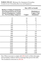
(Also, there is no need for that since NEC has a very easy to use table. I guess the AI can't read the table)

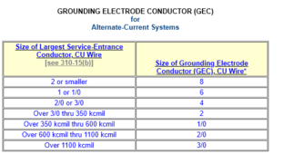
As you can see from the table (first one here is using modern NEC formatting so it should be current), the summary is EXTREMELY confused. LOL. It also doesn't know the difference between GEC and EGC. That's OK, it's being human -- most people on the internet don't know that.
1719781934052.png

(not sure if the following is the latest one, this looks pretty boomer old formatting style, but hopefully somebody comes along and pastes the new one)

1719781963837.png
 
Interpreting your comments, I should be running the solar array (roof-mounted) mounting rail ground back to the main panel.

This ground is an EGC under current NEC.

This EGC must be bonded to both the mounting rail and the solar panels.

Typically the solar panels, when mounted to the rail with appropriate hardware rated to make the bonding connection, are bonded to the rail. Most clamps for solar panels can do that.

(Bonding means electrically sound connection to ground / other metal parts).
 
This is for an off-grid system powering a garage. The system consists of 1 18kpv and 2 wall mount batteries.

1. The load panel is 70 feet from the inverter; I will be running 4awg, 2 feeds, and a neutral. Do I need to run a 4awg ground wire as well or could it be smaller?
2. The grounding rod will be located at the load panel. What size wire should be run from the panel to the grounding rod?
3. Should the solar array mounting rail ground be run to the inverter, the load panel ground, or straight to ground with its dedicated rod?

Previous schematics for the 18kpv recommended a grounding rod dedicated to it. I don't see that on the latest schematics, anyone with some insight?

Couple weird things with the numbers here
  • Load panel 70 feet from inverter. Why don't you just put the inverter next to the load panel? Often sending DC from solar panel is more efficient, since it is at a higher voltage, and the inverter's MPPT input is tolerant to voltage drop along the wire. One argument I can see against this is if you are considering to add a second MPPT or AIO. In which case it is less rewiring to send the power to the garage via a AC cable rather than pulling more PV cables
    • Additionally, 120/240 requires pulling a #8 EGC, 3x #4 for L-L-N. While solar would most likely be OK with #10 EGC and multiple #10s for DC+/DC-.
  • Panel to grounding rod is GEC. I believe #8 is enough to meet code based on the table I shared since your #4 feeder is "2 or smaller". But #6, #4 have arguments for it too because it is future proofed against you adding another inverter or increasing the size of the feeder.
  • What is a "two feeds"?
Don't most California AHJs require a decent level of detail on the SLD that you submit? You can potentially outsource the wire sizing and SLD drafting to Greenlancer.

(as above, this forum has drank the Mike Holt gradient pulse koolaid so very few people still here making noise about grounding will recommend a dedicated grounding rod at the array. I'm not sure if that's what you meant by dedicated grounding rod for 18kpv)
 
This is an excerpt from a google search:

The size of the ground wire you need depends on the amperage rating of your circuit's overcurrent device. You can use the National Electrical Code (NEC) to calculate the appropriate size. Here are some common ground wire sizes for different amperages:
  • 100 amps: 6 AWG aluminum or 8 AWG copper
  • 200 amps: #4 grounding electrode conductor
  • 70 amps: 2 AWG aluminum or 4 AWG copper for a maximum run of 100 feet
In my case, I am running 70 feet. I am getting conflicting information so far.

Interpreting your comments, I should be running the solar array (roof-mounted) mounting rail ground back to the main panel.
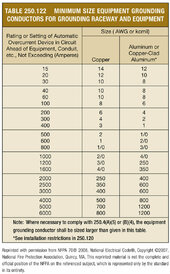
The EGC size is based on the OCP size.
Use this table.
To cover 70a you have to round up 100a requirement.
Which would be #8 copper or #6 aluminum
7uqFA.jpg
 
This ground is an EGC under current NEC.

This EGC must be bonded to both the mounting rail and the solar panels.

Typically the solar panels, when mounted to the rail with appropriate hardware rated to make the bonding connection, are bonded to the rail. Most clamps for solar panels can do that.

(Bonding means electrically sound connection to ground / other metal parts).
Yes, panels are bonded to the rails and I have a ground wire coming off the rails and was wondering about proper earthing. I have read back to the inverter ground bar, back to the main panel ground bar, and a dedicated ground rod for the array/rails
 
Yes, panels are bonded to the rails and I have a ground wire coming off the rails and was wondering about proper earthing. I have read back to the inverter ground bar, back to the main panel ground bar, and a dedicated ground rod for the array/rails

NEC says you just need EGC path back. Main panel ground bar, subpanel ground bar above/below inverter, and inverter AC ground bar are all bonded together anyway, and I believe NEC allows for more flexibility for EGC path on PV circuits than most other circuits. Which is why there are so many answers, and multiple legal ones with different tradeoffs (and devil's bargain, usually improving safety for one thing makes something else less safe).

That admits people to pick their favorite one based on loose engineering superstition. I have not seen testing / math done comparing the different approaches. For instance, one superstition is that they want a voltage pulse induced by SPD clamping to EGC to stay as far away from expensive stuff as possible. Which would argue for bonding to main panel directly instead of first to inverter ground bar and then indirectly to main panel. But if you bond to main panel, then it's maybe more possible for a bonding failure between inverter and main panel to degrade touch safety in other failure modes.
 
Couple weird things with the numbers here
  • Load panel 70 feet from inverter. Why don't you just put the inverter next to the load panel?
This main lug panel was already in place being fed by a 70-amp breaker from the main panel. That wiring has been disabled, the objective is to make this panel the main panel for this structure. It was easier to run ac wire to this area than try to make room for the 18kpv along with 2 batteries
Additionally, 120/240 requires pulling a #8 EGC, 3x #4 for L-L-N. While solar would most likely be OK with #10 EGC and multiple #10s for DC+/DC-.
The 120/240 requiring #8 is where my confusion is. I understand this as follows, If I have 120/240 coming into the main panel I would run a #8 EGC from the panel to the ground rod right outside the structure. In this case, I have the 3x #4 for L-L-N and an EGC coming from the 18kpv load lugs and ground bar respectively. Although the EGC runs 70ft a #8 wire will suffice, is that correct? I do not need #4 awg.
What is a "two feeds"
Sorry. split phase, line one line 2
 
o cover 70a you have to round up 100a requirement.
Which would be #8 copper or #6 aluminum
Yes, thank you for he table. I am running 70ft from the 18kpv ground block to the main panel ground bar, does the #8 copper still apply? I have #8 wire running from the panel to the grounding rod outside the structure.
 
This main lug panel was already in place being fed by a 70-amp breaker from the main panel. That wiring has been disabled, the objective is to make this panel the main panel for this structure. It was easier to run ac wire to this area than try to make room for the 18kpv along with 2 batteries
OK this makes a lot of sense now.
The 120/240 requiring #8 is where my confusion is. I understand this as follows, If I have 120/240 coming into the main panel I would run a #8 EGC from the panel to the ground rod right outside the structure. In this case, I have the 3x #4 for L-L-N and an EGC coming from the 18kpv load lugs and ground bar respectively. Although the EGC runs 70ft a #8 wire will suffice, is that correct? I do not need #4 awg.

The EGC sizing rules are first based on branch or feeder circuit ampacity. If you have a longer run, that causes you to upsize the current carrying conductors to mitigate voltage drop, then you also need to upsize the EGC (I'm not so familiar with this rule, I'm just DIYer and we tend to have tiny lots here in San Mateo County, if you have a property big enough to worry about voltage drop you aren't the kind of person to need to dirty their own hands)

The GEC rule is based on the size of the wire from the power source feeding the system. With a completely off-grid garage, fed only by an off-grid 18kpv, I believe you would use the conductor size coming off the output of the 18kpv. Since it's a separately derived system.

Now, if your 18kpv is connected to grid as backup [A], then you have to use your service conductor sizing. Since you have two power sources, and it makes sense to use the size of the bigger one. Now, what I'm not sure about exactly, is whether a detached structure would use feeder or service conductor sizing. (again I'm DIY'ing in an area where these are purely academic questions for most DIYers so I only have tangential need to be aware of it). This may be why your second ground rod (presumably at a detached structure) has a #8 GEC when your service is likely >100A

Kind of confused with the pre-existing setup here. Main lug implies either non code compliant or old version of code. It is allowed to be MLO if in the same structure as the main panel. But you are also talking about a separate electrode which implies a second structure. I'm not sure if a single structure is allowed to have two non-bonded grounding systems.

([A] which actually sounds more likely than a purely off grid system. if you were purely off grid, why not save a good chunk of money with a 6000XP even in California, by just having everything off the books. I'm sure there are some rural counties where nobody cares)
 
Yes, thank you for he table. I am running 70ft from the 18kpv ground block to the main panel ground bar, does the #8 copper still apply? I have #8 wire running from the panel to the grounding rod outside the structure.
Yes #8.
Distance doesn't matter for the EGC.
 
Kind of confused with the pre-existing setup here. Main lug implies either non code compliant or old version of code. It is allowed to be MLO if in the same structure as the main panel. But you are also talking about a separate electrode which implies a second structure. I'm not sure if a single structure is allowed to have two non-bonded grounding systems.
This is a separate structure, the electrode was added since it is now a stand-alone. The subpanel has become a main panel, hence the ground and neutrals are bonded and the grounding rod was added. All fed by the 18kpv with no grid back-up, decided on the 18kpv just in case it does not work out I can always get the grid backup
 
It does indirectly matter under some NEC if the CCC are larger than the minimum called for by the ampacity of the circuit -- since the EGC needs to scale up to match.
Correct, if the current carrying conductors are increased, due to any derating. The EGC is increased by the same proportion.
I didn't mean to confuse the answer.
I was just stating that the 70' distance didn't make any difference.
 
This is a separate structure, the electrode was added since it is now a stand-alone. The subpanel has become a main panel, hence the ground and neutrals are bonded and the grounding rod was added. All fed by the 18kpv with no grid back-up, decided on the 18kpv just in case it does not work out I can always get the grid backup
OK so it's kind of old, and you have to decide how much you want to upgrade to modern code. I would call the new ground rod mandatory (LOL) even if you aren't getting it inspected. You probably need to add a main breaker if you want to fully modernize.

The 6000XP also has grid backup, will not backfeed, and is UL1741 for off grid. The 18kpv premium of $2000 over 2x 6000XP adds 200A bypass, grid assist instead of just transfer on overload/battery depletion, UL9540, and UL1741SB for export to grid. Feels like a lot of money for the privilege of stuff you're not using 🤷
 
OK so it's kind of old, and you have to decide how much you want to upgrade to modern code. I would call the new ground rod mandatory (LOL) even if you aren't getting it inspected. You probably need to add a main breaker if you want to fully modernize.
That is the 70 amp (lug panel breaker) I have been referring to.
 
That is the 70 amp (lug panel breaker) I have been referring to.
OK, you should be able to put a backfeed breaker on that (if there isn't one already), with a hold down kit to improve safety. That will make it easier to work on electrical in that building when the power source breaker is 70 feet away.
 

diy solar

diy solar
Back
Top