diy solar

diy solar

Proper Grounding.

Not the person to answer your question on the grounding, but very intrigued by your tracker. Anyway to get more pictures and possibly info about the actuators etc. That looks like from the front at least, a very solid stable device. The opposite of the ecoworthy tracker! Thanks
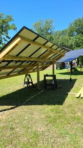
Finished building this in 2019. Tracks by calculating suns position according to longitude and latitude and time for my area. I move every hour on the hour. Sun only goes about 6 degrees. 9" dia schedule 40 pipe came from local scrap yard. linear actuator for tilt, gear motor for azimuth. Biggest Harley sprocket I could find, cut the center out so as to fit the top of the 9" dia pipe. So harley chain drive. I go nearly flat if wind is over 26mph for 6 minutes. I purchased the rails to mount on 5"x 5" square beam 3/16" wall. Braced with aluminum angle. Program runs on esp32.
Sensor is LSM303 mounted on pvc nearly 3 feet from any metal. Two lifeP04 12v batteries in series with cheap Chinese charger from little panel on lefts side of array. The red channel iron was a large I-beam from scrap yard, I cut in half. The slew bearing was used on ebay.

I had code running with lots of work and LDRs first, tossed them when I found this link. I do not use all but his code made me complete!

 
Last edited:
Bypass with what?
The EGC (Equipment Grounding Conductor) needs to be connected to all equipment.
You can't avoid the connection to local earth. (Due to the design of the array support structure)
But that doesn't replace the required EGC.
The electrical grounding system is for safety. An earth connection does nothing for electrical safety.
I misunderstood, so DO connect to tracker then on to the ground array also. I already have the ground wire connected to bare wire running to ground rod at house as the PV conduit enters house right next to it.

20240423_112425.jpg
 
so DO connect to tracker then on to the ground array also.
Correct
I already have the ground wire connected to bare wire running to ground rod at house as the PV conduit enters house right next to it.
That's fine, as long as that bare wire is (and remains) connected to the main systems ground bar. (In the main panel usually)
 
Correct

That's fine, as long as that bare wire is (and remains) connected to the main systems ground bar. (In the main panel usually)
Correct, it does go to main panel. Also I assume, since the ground mount the panels are isolated from each other, I will need to make connections to each panel mount tab then to my ground wire.
 
I misunderstood, so DO connect to tracker then on to the ground array also. I already have the ground wire connected to bare wire running to ground rod at house as the PV conduit enters house right next to it.

View attachment 211407
Off subject but I cannot imagine that structure surviving a 70 MPH wind! It was neatly built but you are in hurricane country! I'm a big fan of supporting the front also. Just my opinion.
 
Off subject but I cannot imagine that structure surviving a 70 MPH wind! It was neatly built but you are in hurricane country! I'm a big fan of supporting the front also. Just my opinion.
It has been through some big storms. Early days before I had the anemometer in the mix, I had to get up at night and run out and manually tilt flat. I have a lot of big trees so most wind never gets to it. I'm north Louisiana. I made first motor mount out of 1/4" aluminum, it got wadded up twice, tossed it and redesigned one out of steel with big rubber roller to take some of the abuse, been working for several years.
 
Last edited:
@timselectric While we are on the subject of grounding, I have another question.
If I have 6 AWG grounding wire and you said everything needs to be minimum 6 AWG along the path, when I go to run the ground wire from my panels (array) back to the MPPT, does the ground need to be 6 AWG solid copper too?

Would you run solid copper?
 
@timselectric While we are on the subject of grounding, I have another question.
If I have 6 AWG grounding wire and you said everything needs to be minimum 6 AWG along the path, when I go to run the ground wire from my panels (array) back to the MPPT, does the ground need to be 6 AWG solid copper too?
For the panels
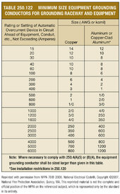
the grounding conductor is sized for the OCP of the circuit it's ran with.
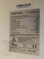
Solar circuits don't usually require OCP, so size it according to the sticker on the solar panels.
Times 2 if 2p, or times 3 if 3p, and so on.
Where exposed to physical damage (not in conduit) . The minimum requirement is #6.
Would you run solid copper?
No
I use stranded insulated (green) conductors.
 
Too long to read every post. So, my free advice .......

Two things to consider: grounding metallic objects that may have a risk of damage from a DC short circuit to ground killing those who come in contact if the current is high. This can come as PV+ to ground or PV- to ground. Not good.

The second is the AC ground. This is the ground that begins at the generation point for AC power. It consists of the hot lines, a ground connection and a neutral connection. In the USA, we have a split phase consisting of an L1 and L2 hot legs, a ground and a neutral. The neutral and ground are bonded together at only one point in an entire AC system. It's either the main utility panel, the stand alone generator or the off grid inverter.
A proper AC circuit will consist of a L1 and/or and L1/L2, a neutral and a ground wire. So 3 or 4 wires. And all metal switch boxes, conduits, fixtures, appliances, electric devices should have a ground connection to prevent electric shock. Neutral should never come in contact with ground except at the 1 identifiable point in the system.

Now, back to DC ground. This really means you need to establish an earth ground point preferably using a grounding rod. This can be at the array, at the inverter or both. So ground all metal at the array to a rod. Run PV+ and PV- to inverter, if off grid, ground inverter and all other items involved in the DC circuit to a grounding rod near this locale. This means the inverter, batteries, metallic conduits and cabinets.

Third option is to pass the DC ground and connect to the AC ground point, but do this outside of the inverter, not at the inverter buss bar. And this is best if using a utility ground IMO rather than a generator bonded ground. Using this method, you will be running a ground wire from array along with the PV+ and PV- in a conduit to make connections. But you still need to ground all parts of the array including panels, mounts, metallic boxes and have them connect to the ground wire going with the PV wires.
 
@timselectric Thanks so much for your generous expertise! My panel says Maximum overcurrent protection of 20A, so could I use #10 jacketed THWN (even though it says #12 on the chart) to go from my panels to the ground outside or bring it into the cut-off switch (only one string so I don't need a combiner box) (midnite solar 30A cutoff switch) and then that goes directly into the MPPT which will be grounded by the 6AWG that is consistent along each thing connected (for lack of a better description-per your instructions, I wired batteries, inverter, transfer switch and panel all together using the 6AWG wire) So could the #10AWG ground wire come from the panels to the breaker/disconnect and then switch from that to the 6AWG to the MPPT? Just having 6-8 panels in one string. Schneider XWPro 600V so keeping it above the 300V sweet spot.

Or, is it allowed by code to attach another acorn to the main grounding rods and attach it there?
 

Attachments

  • E7D7C6EB-80D6-4BEB-ADD5-402D1E280B11.jpeg
    E7D7C6EB-80D6-4BEB-ADD5-402D1E280B11.jpeg
    108.1 KB · Views: 1
Thanks so much for your generous expertise! My panel says Maximum overcurrent protection of 20A, so could I use #10 jacketed THWN (even though it says #12 on the chart) to go from my panels to the ground outside or bring it into the cut-off switch (only one string so I don't need a combiner box) (midnite solar 30A cutoff switch) and then that goes directly into the MPPT which will be grounded by the 6AWG that is consistent along each thing connected (for lack of a better description-per your instructions, I wired batteries, inverter, transfer switch and panel all together using the 6AWG wire) So could the #10AWG ground wire come from the panels to the breaker/disconnect and then switch from that to the 6AWG to the MPPT? Just having 6-8 panels in one string. Schneider XWPro 600V so keeping it above the 300V sweet spot.
All grounding is connected together. How you accomplish that, can be done several ways.
The simplest way is to run an EGC along with any circuit conductors. And connect them together at every junction box or termination point.
And connect to the junction box or equipment enclosure. (If metal)
As long as it's all sized correctly (or larger) for what it's protecting.
The table I posted is the minimum size required. Larger is also fine.
I think we are saying the same thing but using different writing. AC grounding and DC grounding can be separated or connected together. AC grounding is needed at inverter buss bar. DC grounding is not needed inside inverter.
 
I think we are saying the same thing but using different writing. AC grounding and DC grounding can be separated or connected together. AC grounding is needed at inverter buss bar. DC grounding is not needed inside inverter.
There should be only one grounding system, for everything.
Separate systems would have a voltage potential between them.
Which can be a shock hazzard, if someone came in contact with both of (between) them.
 
Back
Top