diy solar

diy solar

Main lug load center wiring

Wineguy

New Member
Joined
Mar 2, 2024
Messages
12
Location
Northern California
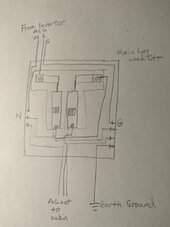
I have an off grid cabin and am getting ready to install a new 48V solar system using a 4 panel array, EG4 AIO 3kW inverter and an EG4 LL-S 48V LFP battery. My question is concerning wiring a 2 circuit single phase main lug load center taking power from an EG4 AIO 3 kW inverter. The load center will only have one 15 amp circuit to power lights and a few plugs in an offgrid cabin (the only AC power is coming from the inverter via the load center).The EG4 manual says that the inverter AC input and output should have a 30 amp breaker and the inverter is grounded to the inverter cabinet. Can I bring in power from the inverter to a lug on one side of the load center and connect to a 30 amp breaker (using it like a main breaker) and then run a wire from the 30 amp breaker out to the lug input on the other side of the load center and then attach a 15 amp breaker to that side of the panel. (see drawing) In essence, instead of running a jumper from one lug to the other side lug and energize both sides of the panel I would like to use the 30 amp breaker as a main breaker and only energize one side of the panel from the inverter and then use the 30 amp breaker to energize the other side of the panel. Also, I am understanding that I need to separate the neutral bus and the ground bus. Is this correct? I plan to run an earth ground wire from the ground bus to a ground rod. This is the only grounding in the system. My 4 solar panels will be installed in series mounted on a metal roof. I plan to ground my solar panel series array with a separate earth ground rod. Should/could I use one ground rod for both or should they be separated and use 2 separate earth ground rods? Thanks in advance for any help!
 

Attachments

  • MainLugPanel.jpg
    MainLugPanel.jpg
    88.5 KB · Views: 18
Disregard the wire size and no neutral bus but this is what I was trying to convey in the thread.
 

Attachments

  • Proposed wiring load center.jpg
    Proposed wiring load center.jpg
    107.9 KB · Views: 21
Input should have a breaker if another source feeds it.

I don't see the point of an output breaker. 3kW inverter can't be expected to trip a 30A breaker, but a 30A breaker could nuisance trip.
Only useful if you accidentally backfeed it from a generator or something, and then only protects inverter if you're lucky.
 
Can I bring in power from the inverter to a lug on one side of the load center and connect to a 30 amp breaker (using it like a main breaker) and then run a wire from the 30 amp breaker out to the lug input on the other side of the load center and then attach a 15 amp breaker to that side of the panel.
Yes, that's fine.
Also, I am understanding that I need to separate the neutral bus and the ground bus. Is this correct?
That depends on whether or not the AIO creates the N/G bond. If it does, you are correct. If not, then you have to create it.
I plan to run an earth ground wire from the ground bus to a ground rod. This is the only grounding in the system.
This is the only ground rod (or two at this location) required.
I plan to ground my solar panel series array with a separate earth ground rod.
Don't do that. You need to run an EGC (ground wire) with the PV wires. And connect it to the rest of your grounding system.
Should/could I use one ground rod for both or should they be separated and use 2 separate earth ground rods?
Only one connection to earth, for the grounding system.
 
Bit confusing your description and the drawing. I will assume you mean Inverter "AC out" for what you are intending to power. "AC in" has to come from a alternate AC supply feeding the AIO. The output breaker after your inverter can be less than 30a if you never intend to exceed it. By running a 30a breaker and appropriate wire size however you can get the maximum power from your AIO if a load exists. Typically the AC output breaker will feed a panel with several circuits. If you are running lights and outlets I would split them with 15a being lights and a 20a being outlets.

ACout ->30a breaker-> Panel lugs (jumper L1 and L2)->branch circuits Label panel as being 120vAC only
 
Disregard the wire size and no neutral bus but this is what I was trying to convey in the thread.

Only 2 slots, if you put 30A in one as a main breaker and 15A in the other for branch circuit, you only get one branch circuit.

Feed Line from inverter through both lugs (strip in middle where it passes through first lug.)
Use two 15A breakers.

That way you have two branch circuits, and there is still 30A total on the inverter.

Or, wire as you're thinking and use a 15A or 20A tandem breaker to feed two loads.

Looks like it would fit Homeline breakers.


Use tandem breaker HOMT3020, backfeeding the 30A pole as main, connect two lugs together, use the other slot for tandem 15A or 20A. That gives you 3 branch circuits.


Or use second slot for GFCI, shock safety for wet locations.

 
Yes, that's fine.

That depends on whether or not the AIO creates the N/G bond. If it does, you are correct. If not, then you have to create it.

This is the only ground rod (or two at this location) required.

Don't do that. You need to run an EGC (ground wire) with the PV wires. And connect it to the rest of your grounding system.

Only one connection to earth, for the grounding system.
Thank you. I will double check that the AIO creates the N/G bond. If so, then I plan to install an insulated neutral bus in the load center. I plan on running 8 awg ground wire from the load center to the ground rod. My PV supply wires are 12 awg. Do I need to run 8 or 6 awg ground wire from the panels to the ground rod? or can I use 10 or 12 awg for that run of about 40 feet?
 
Bit confusing your description and the drawing. I will assume you mean Inverter "AC out" for what you are intending to power. "AC in" has to come from a alternate AC supply feeding the AIO. The output breaker after your inverter can be less than 30a if you never intend to exceed it. By running a 30a breaker and appropriate wire size however you can get the maximum power from your AIO if a load exists. Typically the AC output breaker will feed a panel with several circuits. If you are running lights and outlets I would split them with 15a being lights and a 20a being outlets.

ACout ->30a breaker-> Panel lugs (jumper L1 and L2)->branch circuits Label panel as being 120vAC only
Thanks. Yes, what is described as AC in (to the load center) is from the AIO AC out. AC in to the inverter will not exist unless I install a connection to a small generator. There is no grid power available. PV will power the inverter. I plan to install a 20 amp inline fuse on the positive PV wire and a 20 amp PV disconnect breaker on both positive and negative from the panels prior to the AIO. My series wired PV will supply a total Voc of 194 V and Isc of 10.5 amps so a 20 amp fuse and breaker should work unless I am completely missing something.
 
Only 2 slots, if you put 30A in one as a main breaker and 15A in the other for branch circuit, you only get one branch circuit.

Feed Line from inverter through both lugs (strip in middle where it passes through first lug.)
Use two 15A breakers.

That way you have two branch circuits, and there is still 30A total on the inverter.

Or, wire as you're thinking and use a 15A or 20A tandem breaker to feed two loads.

Looks like it would fit Homeline breakers.


Use tandem breaker HOMT3020, backfeeding the 30A pole as main, connect two lugs together, use the other slot for tandem 15A or 20A. That gives you 3 branch circuits.


Or use second slot for GFCI, shock safety for wet locations.

Thank you. Good idea.
 
That is a very small breaker box. I often outgrow, overstuff mine.
Shop around including on eBay, you might want a 6, 8, 12 slot one and get it cheap.
Full size breakers may cost less than tandem.
 
Thank you. I will double check that the AIO creates the N/G bond. If so, then I plan to install an insulated neutral bus in the load center. I plan on running 8 awg ground wire from the load center to the ground rod. My PV supply wires are 12 awg. Do I need to run 8 or 6 awg ground wire from the panels to the ground rod? or can I use 10 or 12 awg for that run of about 40 feet?
If getting inspection.
Minimum GEC (Grounding Electrode Conductor) is #6.
This is the wire to the ground rod.
If not #10 is more than adequate.

For the PV array EGC (Equipment Grounding Conductor). It's size is determined by the circuit current limit.
If the PV circuit conductors are #12 , the EGC can be #14 or larger (if protected by conduit). And a minimum of #6 for any exposed portion (under the panels running openly).
The easiest place to connect it to your grounding system is in the same location as your SCC (Solar Charge Controller). In the connections area of your AIO.
Since you won't have an AC input. You can use it's ground terminal.
 
Back
Top