diy solar

diy solar

Decoding the DALY SmartBMS protocol

This discussion is interesting and helpful. We are trying to integrate a teensy processor with a Daly BMS (72V 100A) via CAN bus. Has anyone here successfully used CAN Bus to communicate with Daly BMS? If so, grateful if you can indicate details about the specific CAN bus protocol that Daly BMS make use of. We could not find this information in the limited manufacturer documentation.
no info or experience with teensy + CAN bus + Daly BMS :(

your project is really cool in my humble opinion, good luck!☀️???
 
This discussion is interesting and helpful. We are trying to integrate a teensy processor with a Daly BMS (72V 100A) via CAN bus. Has anyone here successfully used CAN Bus to communicate with Daly BMS? If so, grateful if you can indicate details about the specific CAN bus protocol that Daly BMS make use of. We could not find this information in the limited manufacturer documentation.
I bought a CAN adapter and successfully communicated with a DALY 16S 100A BMS using the DALY software - so I know it works and blasting fast it is !!!
On the other hand, I tried to get "behind" the CAN bus protocol and I assume, DALY is just using CAN hardware and run their own protocol on top of that. So it's like RS485 and MODBUS - which many people use synonym while DALY uses UART over RS485 and not any MODBUS protocol.
Same I guess for the CAN protocol in which each client gets a HW encoded address which defines also its priority in the CAN bus system (working in automotive myself, hence my humble opinion here). As the CAN protocol (automotive CAN or OpenCAN or whatever follows the standard) is in its structure well defined and fix, the DALY implementation looks QUITE different. You can find it in the resource section DALY CAN protocol. You can also find it on the DALY website after heavy searching and lots of luck ;)

So, although I did not go down this road, I would start with understanding the protocol implementation by listening into the CAN communication of the two DALY components. I would at least assume, you can't use any CAN stack provided by Teensy enthusiasts, if my assumption is correct.

But please post your findings here and if you're successful, write a small How-To in the resource section ...
 
Last edited:
Anyone know if there is a way to control the Digital IOO GPIO ports DO0-DO3 on the Daly BMS modules?
Must be there for some reason?
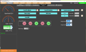
This is a DI/DO-Testing button in their Power App, not sure what it does, DI2 is always high, but no way of controlling the pins to turn things on/off from custom software...

Ive tried writing to the Status Infor 0x94 command with flags for ports set... but nothing happens..
Hidden command? There just for their internal use only? But wonder why they mention the Ports and label them Digital In/Out and have a test button??

1671689076842.png
 
Anyone know if there is a way to control the Digital IOO GPIO ports DO0-DO3 on the Daly BMS modules?
Must be there for some reason?
This is a DI/DO-Testing button in their Power App, not sure what it does, DI2 is always high, but no way of controlling the pins to turn things on/off from custom software...

Ive tried writing to the Status Infor 0x94 command with flags for ports set... but nothing happens..
Hidden command? There just for their internal use only? But wonder why they mention the Ports and label them Digital In/Out and have a test button??

View attachment 125776
I haven't played with the DI/DO myself but I guess, one would need a special firmware on the BMS that allows for it. I had to ask quite nicely for a firmware that let one change the board number (which you obviously mastered already) and I know that there is another firmware that lets one calibrate the current. But unfortunately, if I flash one firmware, the other's functionality is gone. So I assume, DALY can and has to switch on certain functionalities in the firmware at compilation. So you might make a wish list, contact DALY and ask if they would provide. Good luck!
 
I am disassembling the protocol from the firmware for this and it seems on the firmware I have a checksum has been implemented. The format I have so far discovered is:

Code:
Byte 0 = Header, must always be 0xA5
Byte 1 = Unknown still (valid values are 0x40 and 0x80)
Byte 2 = Command
Byte 3 = Must always be 0x08
Byte 4 = Checksum

The checksum calculation is simple, it's just:
Code:
checksum = (uint8_t)(byte0 + byte1 + byte2 + byte3);

There are a heck of a lot of commands that are not yet publicly known, the firmware has sets of commands, and some are extended commands. The below is a complete list of all the short command codes the device sees as valid:

Code:
0x00 - 0x0F = Command Set 1 - Extended Length Commands
0x10 - 0x27 = Command Set 2
0x50 - 0x6A = Command Set 3
0x90 - 0x99 = Command Set 4
0xD0 - 0xDD = Command Set 5

As I discover more I will update THIS post.
 
Hello,
I also want to access information pieces (Soc, Load, Voltage) from Daly, but by Bluetooth.
Anybody that found out more reliable stuff?
It seems there is a lot on github. Tested a lot. Had a lot of errors. Does not work on recent version xyz etc
I also heard about some Daly Documentation for Bluetooth connectivity.
Any help would be highly appreciated.
Thanks.
 
Hi,
I was able to connect to the Daly BMS via Bluetooth and read all the data, but with an older version of the BMS (roughly 3 years old).
The code is on github: https://github.com/mack-c/daly_bms_kelly_controller_display
Maybe it is usefull for you.. The code does a lot more, I was building a display/dashboard for my electric bike. Voltage, current, temperature etc. comes from the BMS via Bluetooth to a ESP32.. ( Youtube moped display )
I found a pdf file online with some information about the protocol. Parts of it worked for me. I can send it to you..
 
Late addition here, but Daly tech support sent me an xlsx file with the documentation on how to use the modbus protocol to communicate with my Daly Smart BMS. I posted it at the link below, along with some snippets of how to use esphome to interface with the BMS.

Note that modbus protocol is quite different from the RS485 and canbus prototocols. You can tell them apart by looking at the first byte of the requests... if it is "D2" then you're seeing the modbus protocol, whereas if it is "A5" then it is the RS485 protocol.
 
Last edited:

diy solar

diy solar
Back
Top