diy solar

diy solar

EG4 18kpv best option for grid connection with 100 amp panel

Yes in my area NEM 3.0 with SCE they rip you off on power you sell back to them. So I'm not too concerned with being able to sell power back to the grid.
You still need an interconnection agreement, might as well get paid for it.

I guess the difference is you don't have to use a 1741SB inverter that is approved for backfeed. Still need a 9540 inverter/battery combo in most parts of California.
 
I ordered a EG4 18kpv, 16 × Solarever 455W (in addition to the 8x 370w panels I laready have), and the new EG4-WallMount Indoor Battery.
Hopefully the missing plural on battery is a typo. You won’t get full power from a single PowerPro battery, much less for very long.

Sounds like you want to essentually do grid shaving?
 
Hopefully the missing plural on battery is a typo. You won’t get full power from a single PowerPro battery, much less for very long.

Sounds like you want to essentually do grid shaving?

No I only purchased one for now. Are you saying one won't be enough to say run my AC during the night when the panels aren't producing power?
 
No I only purchased one for now. Are you saying one won't be enough to say run my AC during the night when the panels aren't producing power?
Depends how much power your AC uses, both peak (starting KW) and running (KWHR for the night). One battery has a recommended discharge current of 160A (8.3KW) with a maximum of 200A (10.4KW), so you really need two PowerPro batteries to be able to get the full 12KW out of the 18Kpv overnight. Also note that a single 14.3KWHR battery will only run _maybe_ a 1.2KW overnight (12 hours, depends on your system how much runtime you need), which is enough for an AC split, but probably not a 5-ton central air system.
 
Am I correct in my understanding that the at night AC can partially be powered by the battery and when the battery runs out the inverter will pull power from the grid?
I do realize the single battery most likely won't be able to fully support all of our loads throughout the whole night but at least offset some of my utilization of the grid from the stored solar power.
I plan on purchasing a 2nd battery and adding it later once I get some ROI from the system.
 
After doing some more research and talking with my electrician friend some more I think this is the plan. Just posting here for a sanity check and if anyone has feedback.

Here’s my current setup:

  • Service: 100A
  • Main Breaker: 100A

Plan​

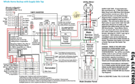
  1. Connection Type: Whole home backup with a supply side tap. As shown in the manual:
    1720631499737.png
  2. Wiring: Considering using 4/0-4/0-4/0-2/0 SER Aluminum Building Wire from the supply side tap to the fused disconnect and then to the grid connection on the inverter.
  3. Fused Disconnect: GE 200 Amp 240-Volt Fusible Outdoor General-Duty Safety Switch
  4. Manual Transfer Switch: GE 200 Amp 240-Volt Non-Fused Emergency Power Transfer Switch
  5. Conduit Size: Planning on using 2.5-inch conduit for the SER cable.

Questions​

  1. Future-Proofing: Is it okay to use 200A rated components (fused disconnect and manual transfer switch) with my current 100A service, considering I plan to upgrade to 200A in the future?
  2. Installation: How should I install the manual transfer switch if my main breaker is on the same bus bar in my panel? Do I need a separate box for this?
  3. Wiring Method: Is the 4/0-4/0-4/0-2/0 SER Aluminum Building Wire appropriate for connecting the supply side tap to the inverter, and should it be run in conduit?
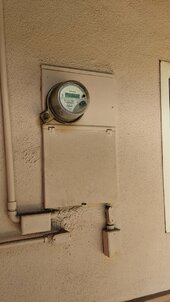
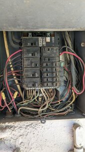
Here are some pictures of my panel for reference:

  1. PXL_20230818_211334607.jpg
  2. PXL_20230818_211448437.jpg
Any insights or suggestions would be greatly appreciated. Thank you!
 
Sure, you can use 200A rated components.

Where is the gas riser here? That is important for what you are allowed to add. Placement and upgrade of electrical components is heavily restricted near gas riser with PG&E

I still am not sure you grok the supply side tap, which is confusing bc you have an electrician on this project and they should have raised at least one of the concerns I raise here. Maybe they’re only loosely consulting. The SLD and flow chart from these manuals need some external sanity checking. Maybe you wrote “move all loads to a subpanel OR convert main panel to subpanel” either in last message or way up and I missed it

For instance, that SLD is not isomorphic to your meter main combo. The SLD shows a main breaker followed by a separate subpanel. And this is core to the wiring approach where the 18kpv is effectively an alternate path to going through the main.

With your combo main, the main breaker is joined at the hip with all load breakers. You can’t separate it without literally cutting the busbar. A combo main also i don’t believe has obvious ways to convert to a subpanel since they have N-G aggressively bonded to each other by their construction. For instance, on a convertible panel the N components and lugs are carefully placed on insulating plastic spacers rather than directly on the chassis. Then extra grounding bonding screw is installed to join if bonding is desired
 
The gas riser is located 30ft away from this location on the other side of the outside of the garage.
So it sounds like with my combo main panel my only real option is to go with a partial home backup with a critical loads sub panel?
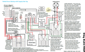
Following the diagram in the manual here:
1720637464763.png
 
The gas riser is located 30ft away from this location on the other side of the outside of the garage.
So it sounds like with my combo main panel my only real option is to go with a partial home backup with a critical loads sub panel?
Following the diagram in the manual here:

You can do full house no problem. You just need to put a 200A subpanel between the combo main and the 18kpv. And then splice extensions onto your circuits in the main, and move them to the subpanel. This is 100% allowed by code. You only have 11 circuits there.

Feed the 200A subpanel from 18kpv with 200A feeder (You can potentially pick 100A or 150A too, but might as well just do it right the first time)

Add a big enough conduit between the combo main for you to extend all your circuits through (if you keep it under 24", aka nipple rule, you can use a smaller conduit and skip derating calculations, which will allow you to jam a ton of circuits through it beyond what a >24" will allow). Keeping extension short also avoids triggering AFCI replacement.

As a huge bonus, now you have space for adding more circuits. Your meter/main was full.

You can add an 18kpv bypass if you want

 
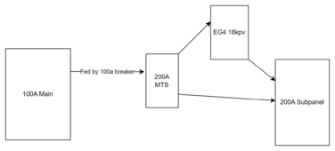
That sounds like a great option. How would you suggest I do the 18kpb bypass? One of concerns with the critical loads subpanel is if the inverter fails those circuits would be without power until I can replace the inverter or move them.
Would it look something like:
1720643235903.png
 
I agree with Tim.

Also 200A transfers are more expensive than 100A

There are some people here that decided to just splice things together with Polaris style connectors that are set up to be rapidly reconfigurable. More compact and cheaper but someone needs to know how to redo the splices. Not something you can delegate to random family members, while a child can use the bypass switch.

Some MTS also may qualify as lockable solar isolator, so if your AHJ aggressively requires that you can try to kill two requirements at once
 
At 200A though?

(I think OP has 100A but wants to future proof)

In a lot of California lockable knife disconnect is not needed.
I would stick with 100a.
No need to upgrade to 200a, until they are ready to rebuild everything.
Besides, they will never need 200a.
 
I would stick with 100a.
No need to upgrade to 200a, until they are ready to rebuild everything.
Besides, they will never need 200a.

I would do it this way too. Also, by the time they need 200A, California will have adopted NEC2023, and that version rephrases 220.87 load study in a way where you can use an ESS to justify adding more loads to a house. IE, by letting the ESS eat the load from existing or new appliances.
 
Nobody will ever need more than 640K of memory in a PC. Something about using always and never. In the words of another "C'mon man"? Your gonna spend $10K, do it the way you want. Tim is a cheapskate.

I will wire this puppy up this weekend, shuffling some boxes around. For now my inverters are behind this wall with the sub-panel. In the future I will drop another conduit in the box to an outbuilding that will house the power plant, along with a conduit for the 4 PV runs on the roof.

$150 ATS 160A Identical 200A unit is $250, see below
$150 16x24x10 outdoor box
$300 all in

I went for the amazon knock off for these . . .
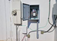
https://www.ato.com/automatic-transfer-switch-100-160-250-amps which will run you $350ish. This bad boy appears to be pretty heavy duty, I'm using the very small chinese units inside next to the panel at the moment. I had one die, I replaced it but it prompted the upgrade ahead of schedule.

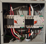
In for a penny, but I think it's a really good idea to have a bypass to your other panel, and I'm kicking myself for not just going ahead with a 200A panel. Easy enough to de-rate it to 150 or 100 with a different breaker. I'll be feeding the ATS with a 100A breaker on the meter panel on the secondary. The switch is 3-position, Primary - Common, Secondary - Common, Open (Manual with the handle, current position.) I like being able to turn sh*t off or move it manually if need be. I may use crimp lugs instead of the hex. Had to get $100 worth of wire, how much more you might need to inline an ATS is hard to say.
1720654212426.png
 
One other option would be to make the load side of the AIO 200a to the main breaker of the sub panel. And the grid bypass a 100a interlocked breaker.
 
Run 70A from the grid panel to the generator input, let it do generator assist as needed.

That's not a bad idea.
Like I think I said earlier I'm looking to get this system up and running as soon as possible in the most cost efficent way so it can start paying for itself. As soon as summer hit my SCE bill went from about $350/mo to my next one is on track to be $850!
Setting up a sub panel and moving my loads over even slowly if I just get my AC on the solar will be a big savings.
 
FWIW my personal extreme bias against bothering with 200A anything is because my riser is within 12” of my MSP, so I can’t change anything (including service size, or even a higher busbar panel) without paying $10-20k to relocate first. It costs that much because service conductors are underground and not allowed to be spliced before meter

So qualify my advice against that
 
We are talking trimming an $800 electric bill. Set up a sub-panel where you can move the feeds from the current panel/ DIY $200. Wire it up behind an ATS, you can skip the box if it's inside, feed the ATS from the grid panel, use #2 for the wire, 100A breaker, and from the inverter direct. ATS to panel 100A breaker there as well. Turn things on, verify operation of ATS, get happy with DMM. Flip breakers on and off make sure everything is as expected. Move something to the panel.

I will note I am biased, as this is exactly what I did. I used one of those cheesy 100A ATS's to start with The one on the right below. It died after a little over a year in service, about 9 months of duty actually switching every day. I had a spare ready so annoying, but not overly reliable, thus the more robust switch above will be taking it's place.

Just let the inverter fall over when the batteries are done, the ATS kicks you back to house power. Synchronizing with the grid is somewhat problematic, but useful. I have two inverters and accomplish the task by connecting only 1 grid input, but I think the firmware is fixed up enough to tie to the generator without actually using it. Might take some fiddling with the settings, or just deal with the phase jump. Make sure you have a Micro-Air on your AC. Start saving money. Take the savings expand the system.

1720666923018.png
 
NOTE: Left ATS feeds a charging pedestal outside for the EV. It is goofy, cross connected on the control side. The top/primary feed is from the sub-panel, bottom from the grid panel. Top feed is used to provide control power to activate the bottom, so when the grid breaker is OFF there is simply no power at the pedestal. Top control is activated by software, basically creates a software controlled relay to allow feed from the sub-panel, with a manual bypass to use the grid if needed.
 

diy solar

diy solar
Back
Top