diy solar

diy solar

Dual EG4 6000XP Wiring (please review)

solarenvy

Solar Enthusiast
Joined
Feb 2, 2023
Messages
94
Location
Virginia, USA
Hi diy'ers. I have used much of what I've picked up on a number of different threads (mostly: https://diysolarforum.com/threads/eg4-6000xp-ac-out-load-wiring.73268/) to come up with a wiring diagram that I think will work for my off-grid setup in a remote cabin:

- 2 x EG4 6000XP, off-grid with grid backup
- Combined for maximum AC output (50A) + pass-through (100A)
- Support for all-grid bypass (emergency, maintenance, etc.)
- Fall back to grid AC only when absolutely necessary
- N/G bond disabled at each inverter
- N/G bond ONLY at main panel
- 10X Solarever 455W PV (going to 20X)
- 5X (25kwh) EG4-LLv2
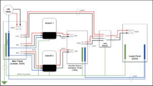
1707161410861.png

Some questions:

- does this look reasonable / safe?
- should all the grounds be home-run to the main panel (vs. next hop)?
- are the breakers correctly sized to support max inverter AC output and grid pass-through?
- anything else?

Any help/advice is greatly appreciated...and thanks to all that have already contributed to get me to this point.
 

Attachments

  • Dual 6000XP Wiring v1.pdf
    98.2 KB · Views: 26
What does the manual tell you ???
So I downloaded the manual and see......no wiring diagrams !!!!
There is a crap ton of everything you need to know about the inverter, except a wiring diagram.
I think they got shy about offering usage scenarios after the previous fights about transformers and bonding.
Anyways, the manual does suggest 8AWG so make sure your 6AWG will fit the terminals and I would run the neutral from the inverters to the combiner panel too.
Looping the ground to each unit/panel is fine.
 
I'm presently installing almost the exact same setup. One question I have is what is the reason for configuring the output side for maximum pass thru rather than maximum inverter output? Why would you load your output panel more than the inverters can supply? I understand it on the input because of output load + battery charging load but on the output? My understanding is the 6000XP's don't blend grid and inverter.
 
I'm presently installing almost the exact same setup. One question I have is what is the reason for configuring the output side for maximum pass thru rather than maximum inverter output? Why would you load your output panel more than the inverters can supply? I understand it on the input because of output load + battery charging load but on the output? My understanding is the 6000XP's don't blend grid and inverter.
Each inverter can pass-through 50A [from grid] for a 100A combined pass-through. I'd like to be able to pass-through up to the full 100A in a situation where the load demand requires anything greater than the combined AC output of the inverters.

Maybe @AZ Solar Junkie can confirm I'm thinking of this properly.
 
What does the manual tell you ???
So I downloaded the manual and see......no wiring diagrams !!!!
There is a crap ton of everything you need to know about the inverter, except a wiring diagram.
Exactly :)

Would love to see more published examples from the manufactures, for 2 or 3 different scenarios. Stamp a huge "EXAMPLE ONLY" with a full page of disclaimers for all I care.
 
I understand that but why would you load the output to overload the inverters? In my case I'm not going to add more load in my critical load panel then the inverters can output. I'm not sure if the inverters will hold up if you routinely overload them. If your loads panel is an existing house panel I would not be comfortable configuring this way. Your diagram is really nice by the way.
 
All loads will be on the inverters full time (i.e. no separate critical loads panel). I expect to remain under 50A most of the time, but do expect to go beyond that on occasion -- sometimes expected, sometimes not. What I definitely don't want is everything shutting down because demand is too high. While I will do my best to avoid such situations, I have to design the system to handle it. If it turns out that I'm consistently over 50A, it will be straightforward to add another inverter.

I'm not sure if the inverters will hold up if you routinely overload them

This statement is concerning. I don't (or didn't) expect this to be an issue -- @Markus_EG4 are there any datapoints for this? Is there a reason to proactively avoid switching to grid too frequently?
 
As far as I am aware the 6000XP is only rated for 50A output at 120v and can surge slightly higher for 3.5s. I would not believe there should be a reason to avoid switching to grid frequently, however, I will check to see what datapoints we have for this.
 

Attachments

  • EG4-6000XP-Inverter-Spec-Sheet.pdf
    174.4 KB · Views: 21
Each inverter can pass-through 50A [from grid] for a 100A combined pass-through. I'd like to be able to pass-through up to the full 100A in a situation where the load demand requires anything greater than the combined AC output of the inverters.

Maybe @AZ Solar Junkie can confirm I'm thinking of this properly.
Absolutely. I do 50 amp breakers and 6 gauge wire for the grid input to each inverter, and a combiner panel with 50 amp breakers for the outputs.
 
Another issue is you will have tied your off grid inverters to the grid which they are not rated for. The power company will definitely take issue. If the grid goes down you will back feed the grid.
 
Another issue is you will have tied your off grid inverters to the grid which they are not rated for. The power company will definitely take issue. If the grid goes down you will back feed the grid.
I don’t see anyone here talking about connecting the outputs to back feed the grid…
 
Another issue is you will have tied your off grid inverters to the grid which they are not rated for. The power company will definitely take issue. If the grid goes down you will back feed the grid.
The 6000xp is an offgrid inverter. the Grid connection only draws power from the grid, it does not supply power to the grid. At least, as long as it's wired up correctly. The power company doesn't know or care about it's existence. To them, it's just another electrical appliance drawing power from them.
 
What he says in post #8 leads me to believe that bypass block doesn't actually exist. As drawn it wouldn't but his reply indicates something else.Now that I re-read it it seems he believes the inverters will just switch to grid on overload but I'm thinking they just shutdown with a fault. So your right as long as the bypass is switched to inverter it shouldn't back feed.
 
As drawn it shows a 100A bypass. It could just be a 100a breaker in his main panel with a generator interlock. That's what I'm doing in my critical load panel.
 
Back
Top