diy solar

diy solar

EG4 6000XP AC out load wiring?

So, yours will be exactly the same only totally different. ?

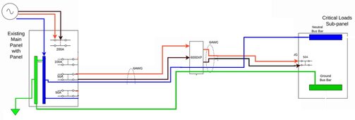
Like this?
View attachment 185755


No... You do not need to do anything with the N-G bond. Just make sure the dynamic bond bond relay in the 6000XP is disabled.

Notice that on the 6000XP, there is no disconnect of the neutral (or ground). That is I drew them as passing straight through the inverter. Consequently, the Neutral and Ground at the critical load panel are 'bonded' by the main bonding jumper at the Main panel.

Yep that looks right. Just passing through the neutral and ground all the way to the CL panel. 6000XP set to disable the N-G bond. In this instance if I’m moving over my office circuits… can I just move the hots or do the neutrals need to go too? Using Wago connectors to extend the wires to the CL panel.
 
Yep that looks right. Just passing through the neutral and ground all the way to the CL panel. 6000XP set to disable the N-G bond. In this instance if I’m moving over my office circuits… can I just move the hots or do the neutrals need to go too? Using Wago connectors to extend the wires to the CL panel.
Electrically, you only have to move the hots and it will work just fine.

I have heard mixed opinions on whether the NEC allows that. Maybe one of the master electricians on the forum can weigh in on this.
 
I have a commercial electrician friend and we spent a few hours looking over the space to come up with the best solution. He suggested we use a 4x4 trough between the two panels, at the ceiling. Then move all 3 conductors for each circuit I want to run - hot, neutral, and ground. Not worth it to not move the neutrals over. Doesn’t make sense to leave the ground behind and I can pull the whole romex out of the top of the breaker box and into the trough. Then extend them with Wago straight through connectors landing in the new breaker box. Approx 6 total circuits to start.

We will run the 220v wires for inverter grid power in a different conduit below the boxes. All new equipment will be mounted on top of Hardie concrete board. PV will be brought in via metal conduit. I can’t wait to share the resulting setup.

Given this new arrangement - I believe the inverter’s N-G bond should be enabled.
 
Given this new arrangement - I believe the inverter’s N-G bond should be enabled.
It is very unlikely the new arrangement will need the NG bond relay in the inverter enabled. I have yet to see a layout where I would recommend enabling the bond in the inverter. Could you please provide a wiring diagram of the system?
 
Reasoning was for starters I’m not going to connect to the main panel for any grid power. So only N-G bond source is the inverter to the 6 circuits. Sorry, I didn’t make that clear above.

Hopefully EG4 offers a dynamic N-G bond option via firmware update. Then when/if I ever need pass through grid power the main panel can provide the bond.
If there is no other bond in the system, put one in the critical load panel and disable it in the inverter. (Why use a relay when you can use a much more reliable jumper?)
 
Yea, that’s better. When I connect the 8 awg wire for grid pass through I’ll have to determine if that still holds true. As soon as I send the neutral in the garage panel to the inverter and, ultimately, the critical load panel it should probably use the house N-G bond.

A part of me wonders though if the 6000xp even needs the neutral for grid input since it wants a 220v connection. Even Will used a 6-50P (two hots and a ground, no neutral) for that connection on his dual 6000XP video.
 
Last edited:
FilterGuy, If the neutral and ground are bonded in the man panel, then do they both need to be run to the 6000xp?
yes, the SINGLE N-G bond in the main (first disconnect panel) is for safety reasons to assist in tripping breakers upon a short


L1 to N is 120v
L2 to N is 120v

to provide 120v circuits for 120v loads - MOST circuits are these types in a US house

L1 to L2 is the 240v for 240v loads
 
FilterGuy, If the neutral and ground are bonded in the man panel, then do they both need to be run to the 6000xp?
Yes.

You may want to review this about grounding:
 
FilterGuy, I am wrestling with the same question of how to handle the output of a 6000xp to a subpanel driving some 240v and 120v loads. I am in new construction.

In my old Growatt, I just ran the 240v (black and white) and ground from the main panel and got the same back from the inverter to power the sub panel and it worked perfectly. So the potential between ground and white and ground and black is 120v so surely ground and white can't be bonded in the main panel?

I am assuming that the red-black returning from the 6000xp inverter is 240v so my question is how do I connect the ground and neutral to the sub panel? With Growatt I had ground and white connected in the sub panel

Also, in your diagram you have neutral and ground bonded in the main so why run both wires to the sub panel if they are connected, surely one wire would do the job?

Thanks for all your comments.
 
In my old Growatt, I just ran the 240v (black and white) and ground from the main panel and got the same back from the inverter to power the sub panel and it worked perfectly. So the potential between ground and white and ground and black is 120v so surely ground and white can't be bonded in the main panel?

There should be two hots, a neutral, and a ground for 240v. The hots can be both black, or one black one alternate color (like red or blue). Neutral is usually white. Green ground.
But still… 4 wires Is what you want to bring over from the main panel to inverter… then continue (pass through) the neutral and ground to the sub panel from the inverter. In this way the sub panel and inverter are using the N-G bond at the main panel.

Heres how I wired mine… image from page 4 in this thread.
Red & Black - hots
Blue - neutral
Green - ground
30F59856-F31C-489C-BFE1-51BCF2ECC6B7.jpeg
 
In my old Growatt, I just ran the 240v (black and white) and ground from the main panel and got the same back from the inverter to power the sub panel and it worked perfectly. So the potential between ground and white and ground and black is 120v so surely ground and white can't be bonded in the main panel?
What Growatt model were you using? Are you in North America? If so, something seems wrong with the description (or I am misunderstanding)

Also, in your diagram you have neutral and ground bonded in the main so why run both wires to the sub panel if they are connected, surely one wire would do the job?
At first glance, it does seem strange to run both wires. However, once you understand how the NG bond clears a fault it does make sense. Rather than cover it here, please review this document:

 
Attached is a deck I used for training about grounding and bonding. It should help you understand why both wires are needed.

Edit: Corrected some typos in the presentation.
 

Attachments

  • Grounding-Bonding-101 clean.pdf
    346.1 KB · Views: 27
Last edited:
You might want to go with larger breakers and wire gauges given that although the 6000XP inverter output max is 25 amps, but when in bypass mode it will pass up to 50 amps directly from the AC grid inputs to the outputs.
That's how I had it setup for my 6500's and that's what I'll continue to use for my new 6000. 6 awg wires with 50 amp breakers.
 
My setup is similar, but without the switch between the combiner panel and the CL panel. Instead an electrician installed a generator interlock switch so that only one source can power the sub panel at a time. I installed a lockout clip to the 100a breaker in the main panel for extra peace of mind.

After reading this thread I see I should disconnect both my neutral and ground wires going from the inverters to the combiner panel.

The problem I am currently having is that I keep getting an EPS overload warning from the main inverter. (Also they are configured for parallel, but only the main inverter takes on any of the load) - Will disconnecting the neutral and ground loops fix this?

[EDIT] - Turns out I forgot to turn the EPS switch on the secondary inverter on - that fixed the lack of utilization for parallel. I'll keep monitoring and seeing if I can figure out the overload issue.

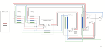
Here's my wire diagram:

1707073865622.png
 
Last edited:
My setup is similar, but without the switch between the combiner panel and the CL panel. Instead an electrician installed a generator interlock switch so that only one source can power the sub panel at a time. I installed a lockout clip to the 100a breaker in the main panel for extra peace of mind.

After reading this thread I see I should disconnect both my neutral and ground wires going from the inverters to the combiner panel.

The problem I am currently having is that I keep getting an EPS overload warning from the main inverter. (Also they are configured for parallel, but only the main inverter takes on any of the load) - Will disconnecting the neutral and ground loops fix this?

Here's my wire diagram:

View attachment 193335
I don’t think disconnecting the shared N and G would fix an overload situation. I know it’s controversial but I think having the G and N going to the subpanel is correct.
 
My setup is similar, but without the switch between the combiner panel and the CL panel. Instead an electrician installed a generator interlock switch so that only one source can power the sub panel at a time. I installed a lockout clip to the 100a breaker in the main panel for extra peace of mind.

After reading this thread I see I should disconnect both my neutral and ground wires going from the inverters to the combiner panel.

The problem I am currently having is that I keep getting an EPS overload warning from the main inverter. (Also they are configured for parallel, but only the main inverter takes on any of the load) - Will disconnecting the neutral and ground loops fix this?

[EDIT] - Turns out I forgot to turn the EPS switch on the secondary inverter on - that fixed the lack of utilization for parallel. I'll keep monitoring and seeing if I can figure out the overload issue.

Here's my wire diagram:

View attachment 193335
You don't want to disconnect neutral and ground from the inverters to the combiner panel and on to the sub panel. I WOULD eliminate the neutral and ground from the sub panel to the main panel, though. Having them connected between the sub panel and the main panel won't fry anything, but it does create loops on both your neutral and grounds which can possibly create issues with RF noise that can interfere with things like Wifi and Bluetooth.

It's probably just a mistake, but your diagram shows ground from the main panel being connected to neutral in the main panel, and neutral going to ground. Definitely not what you want. Again, I wouldn't directly connect neutral and ground from the sub panel to the main panel at all. Earth ground should only go to the main panel in any case.

Finally, as you have spec'd this out, the breakers are only going to support the max inverter output, but won't support the 50 amp per inverter bypass. Should your loads ever exceed 6000 watts on a leg for more than a few seconds, the inverters will automatically switch to bypass and try pulling and pushing up to 50 amps if your loads are big enough. They might not be, but personally I would spec the components to support that. 50 amp breakers for the back-fed breakers in your combiner panel, 100 amp for the output to the sub panel, to a 100 amp in the sub panel. 50 amp breakers in the main panel for the grid input to the inverters.
Thanks for the input,

I'm on the fence about disconnecting ground+neutral from the main panel to the sub panel - the main reason being is so that the solar system can be switched off and disconnected but then the sub panel can still be powered directly from the main.

No - it's not a mistake. This is an 80s/90s era house. The Neutral and ground are combined into one giant bar - so thus the main panel is permanently bonded. (I've had two separate electricians look at it and both have told me there is no reason to change it or the main panel)

And yes - you are 100% correct about the load, breakers and wiring. My intention at least, is to not draw more power than the 25 amps per inverter since that is the max it can supply of non-grid power. My intention is to power all low power devices and leave the heavy loads (range, AC, and dryer) on the main panel.
 
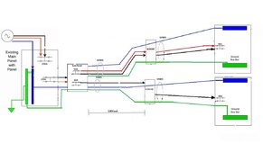
Hello. I’m hoping to get some advice on my upgrade plan. I have upgraded my system a couple of times and now I’m ready to get get more serious.
I currently have a LV6548 with 2000 watts of solar and 272 ah of storage.
Wanting to add on a EG4 6000XP, 18/415 watt panels and 3 SOC 100 ah server rack batteries.

My equipment is in a shed 100’ from my main and where I want to put the critical load panel so it’s a long run. My original idea was to run the AC into both inverters individually from the sub panel I have on the grid panel. The sub has 100 amps 240v of power. And then run back to the critical load panel. I only have a few lights and some plugs in the shed. I have read this entire post and many others and they have been very helpful to expand on my diy knowledge.

One of my challenges is I’m not sure if the 3 awg cable will fit in the 6548 lugs. Any ideas and any input to my plan would be greatly appreciated.
Thank you in advance.

image1.jpeg
 
Last edited:
Back
Top