diy solar

diy solar

EG4 18kPV battery connection, I already have ring terminals

dielectric

New Member
Joined
Dec 5, 2022
Messages
82
Hello, friends
The monster inverter has just arrived. ("EG4 18kPV" by Luxpower).

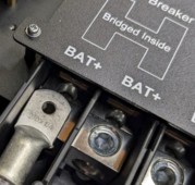
It has what looks like a large set screw for connecting battery cables. Same for grid & load.
While grid and load wires I have are multi-strand but the stiff kind they will work with a set screw
But my battery wire is a "welding" type of fine-strand 2/0.
The monster EG4 is replacing something else and I already have very well crimped terminals on them wires sized for M6 or M8 (don't remember exactly).

What is the accepted way of doing this ?

I can cut off the rings and keep what's left as a "ferrule".
I don't think torquing the screw on those fine strands is a way to go.

[Edit] Adding the picture below.
There are very attractive studs with nuts that would likely fit my existing lugs very well.
All I'd have to do is to remove 4 screws and lift the panel a little bit to undo the nuts and attach the terminals.
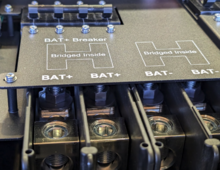
1721179699147.png

Thank you
 
Last edited:
I could also cut or fold in two the lugs and tighten them down under these set screws.
But I'm generally saddened by having to monkey around.

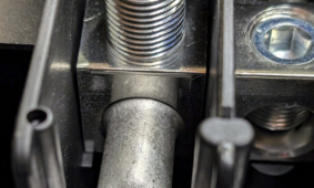
Oh one more idea - remove the set screws and replace them w. bolts with same thread and just use the terminals that way.
1721180227342.png
hmm these are M16? 15.6mm - my thread gauges don't go that far

Here is the variation where I could cut the flat part off:
1721180445749.png
Seems the simplest, it's just a shame to ruin a perfectly good terminal.

And the least destructive is to use a flat piece of copper bolted to the terminals on one end and tightened under the set screw on the other.
I do have some 1/8"x1"flat stock I bought for my battery DIY

What do you all think?
 
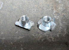
Here is my solution. I really didn't want to screw with naked wires nor cut off perfectly good terminals
1721595809492.png
5/16" t nuts cut to fit the opening
1721595912468.png
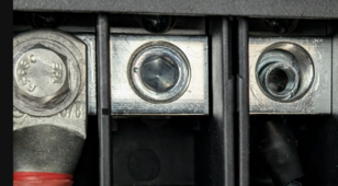
You can see the t-nut in the set screw hole on the right.
I had to use a little wire off-cut to hold it in place.
And the red (positive) on the left if what the result looks like.
 
One more thing.
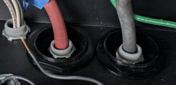
My previous inverter was connected with 3/4" liquid tight. I do not have room for those giant gutters.
Here is how they got attached to the new EG4 18kpv:
1721596137862.png
I drilled the supplied plugs.
I realize it wouldn't work if you had 2 sets of battery wires.
But may help someone.
 
I think I would have just cut off the lugs. It takes a couple seconds to do. And lugs are cheap on Amazon if you ever needed to add them in the future.
 
Also the manual recommends 2-2/0. Or 1- 4/0 battery cable. So if you’re going by the book, you’d need another set of those cables connected.
 
Also the manual recommends 2-2/0. Or 1- 4/0 battery cable. So if you’re going by the book, you’d need another set of those cables connected.
Thank you.
I did read the manual. And some specs on 2/0 vs 4/0. My cables are 20" long if that. And load is not 12KW, not much over 8 in fact. This whole thing is a bit of an overkill.
I might buy 4/0 when I get around to it. Even occasional 200A will be ok through the 2/0.
 
Thank you.
I did read the manual. And some specs on 2/0 vs 4/0. My cables are 20" long if that. And load is not 12KW, not much over 8 in fact. This whole thing is a bit of an overkill.
I might buy 4/0 when I get around to it. Even occasional 200A will be ok through the 2/0.


Yeah technically 1 set of 2/0 will probably do it. It’s not all about output though, you can also charge at 250amps. So wire sizing is definitely one of those things I don’t like to skimp on personally. Large wires just keep things nice and cool.
 
One more thing.
My previous inverter was connected with 3/4" liquid tight. I do not have room for those giant gutters.
Here is how they got attached to the new EG4 18kpv:
View attachment 230199
I drilled the supplied plugs.
I realize it wouldn't work if you had 2 sets of battery wires.
But may help someone.

I don't think you're supposed to have a ferrous closed ring like those lock nuts around half of a circuit. NEC has specific rules about it; I don't know if there is an exemption for DC. If you did this in a steel enclosure you're supposed to cut a notch to interrupt eddy currents. Maybe there's a non-ferrous version you can buy.
 
I don't think you're supposed to have a ferrous closed ring like those lock nuts around half of a circuit. NEC has specific rules about it; I don't know if there is an exemption for DC. If you did this in a steel enclosure you're supposed to cut a notch to interrupt eddy currents. Maybe there's a non-ferrous version you can buy.
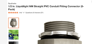
You mean the UL listed electrical conduit is not to be used around wires?
lets remove misleading comments please
this is from home depot website, ul listed
1721613740266.png
 
You mean the UL listed electrical conduit is not to be used around wires?
lets remove misleading comments please
this is from home depot website, ul listed

I don't think what I said is misleading.

Just because it's UL, doesn't mean it's applicable to all ways you can physically put things into them. You need to know the code around the proper use. Another example would be exceeding the conduit fill. Actually I'm pretty sure you're way over the conduit fill. It would be 60% for 24" or less and 53% for longer. You have completely filled the conduit with that.


Simplified code compliant install -- all conductors from the same circuit are supposed to go through the same metallic hole and the same conduit.

There are exceptions but you need to know code better to use them.


And here is a thread on slotting to support my assertion that you need to be careful with the kind of separation you have. Slotting is the way to cut a ferrous box to break the eddy current loop.

 
It's also likely that your modification of the screw terminals to accept lugs is not a code-compliant modification. Screw terminal directly into bare cable (or listed ferrules, if allowed by the manual) is what the designer intended and what the NRTL tested.
 
Hello, friends
The monster inverter has just arrived. ("EG4 18kPV" by Luxpower).

It has what looks like a large set screw for connecting battery cables. Same for grid & load.
While grid and load wires I have are multi-strand but the stiff kind they will work with a set screw
But my battery wire is a "welding" type of fine-strand 2/0.
The monster EG4 is replacing something else and I already have very well crimped terminals on them wires sized for M6 or M8 (don't remember exactly).

What is the accepted way of doing this ?

I can cut off the rings and keep what's left as a "ferrule".
I don't think torquing the screw on those fine strands is a way to go.

[Edit] Adding the picture below.
There are very attractive studs with nuts that would likely fit my existing lugs very well.
All I'd have to do is to remove 4 screws and lift the panel a little bit to undo the nuts and attach the terminals.
View attachment 229088

Thank you
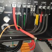
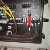
I agree with what you're saying about the fine stranded wire. I used 20awg ballast wire and moused the fine stranded wire and then tightened the lug down on top of it

20240528_062744.jpg20240528_020517.jpg
I've been using this method for over 25 years always make sure the wire is very clean and embedded with no ox inhibitor to prevent corrosion.

This prevents The Wire from fanning out and breaking strands when you bear down on it with the lug.

This makes for a very good connection often use this on diesel starting battery cables and welding leads.

It appears you are beyond this point but this might help you in the future good luck with your installation.
 
I don't think what I said is misleading.

Just because it's UL, doesn't mean it's applicable to all ways you can physically put things into them. You need to know the code around the proper use. Another example would be exceeding the conduit fill. Actually I'm pretty sure you're way over the conduit fill. It would be 60% for 24" or less and 53% for longer. You have completely filled the conduit with that.


Simplified code compliant install -- all conductors from the same circuit are supposed to go through the same metallic hole and the same conduit.

There are exceptions but you need to know code better to use them.


And here is a thread on slotting to support my assertion that you need to be careful with the kind of separation you have. Slotting is the way to cut a ferrous box to break the eddy current loop.


1721715866729.png
... just to be sure you have the full context: those are battery cables and are most likely not "carrying alternating current"
so there is no ferrous ring or other inductive heating concerns

and yes, mister Wizard, I've overfilled the 3/4" conduit with the single DC wire, you are correct.
2/0 cable is about 1/2" diameter and 3/4" conduit is well ... 3/4" 😊, so that'll be 66%
and I might fix it one day if I ever find it warmer than 30C

Are you a code inspector by any chance? So serious.
:LOL:
 
... just to be sure you have the full context: those are battery cables and are most likely not "carrying alternating current"
so there is no ferrous ring or other inductive heating concerns
Thanks for the quote, I missed the AC part.

Sounds like are aware of the risks.

I actually thought I searched for whether there was a DC exclusion b/c it didn't really make sense for DC to cause eddy current as a rule, unless they were hedging against induction from pulsed DC (there's some stuff in NEC that I don't think factors pulsed DC correctly, but that's a completely different issue). Oh well.
 
I agree with what you're saying about the fine stranded wire. I used 20awg ballast wire and moused the fine stranded wire and then tightened the lug down on top of it

View attachment 230279View attachment 230278
I've been using this method for over 25 years always make sure the wire is very clean and embedded with no ox inhibitor to prevent corrosion.

This prevents The Wire from fanning out and breaking strands when you bear down on it with the lug.

This makes for a very good connection often use this on diesel starting battery cables and welding leads.

It appears you are beyond this point but this might help you in the future good luck with your installation.
I am kinda surprised they went with these set screw things. A lot of other equipment takes ring terminals.
I appreciate that this is less work for the installer, but I'm not an installer.
I'm a tinkerer and will inevitably take these apart for some reason or another and loose strands will only survive the remake a limited number of times.
The previous inverter this beast replaced had ring terminals with M8 bolts. I bought me a nice and cheap hydraulic crimper and loved the results.
 
Thanks for the quote, I missed the AC part.

Sounds like are aware of the risks.

I actually thought I searched for whether there was a DC exclusion b/c it didn't really make sense for DC to cause eddy current as a rule, unless they were hedging against induction from pulsed DC (there's some stuff in NEC that I don't think factors pulsed DC correctly, but that's a completely different issue). Oh well.
I appreciate the codes, I do. But I'm also an engineer that invents sh.t all the time. So I take "suggestions" from NEC and I do value advice from people with hands-on experience. And then try to make it work in 1/3 of the space for 1/4 of the cost :)

I had to remove the latches from the right side of the unit because I only had about 1" of space left 🤣
Replaced them with a couple of electrical box knockouts drilled and bent + bungee cords
Not to worry there is a large exhaust fan in that wall and the wall is fibercement.
1721717456155.png
 

diy solar

diy solar
Back
Top