diy solar

diy solar

Accessing Deye RS232 port from SBC instead of datalogger

squarefoot

New Member
Joined
Jul 26, 2024
Messages
5
Location
Rome
Hi everyone, I just signed up to the forum; not sure about where to post my question, so here it is:
After moving to a new house and paying a few absurdly high heating bills this winter, I rushed to do what I already had planned to do in a few months and had a complete solar system installed, with a Deye SUN-6K-SG05LP1-EU inverter plus 3xUS5000 Pylontech batteries. I'm not 100% sure about the exact inverter model because all papers are upstairs, but it's a single phase model for EU market. Now the problem: I don't want to share my solar data with external servers, or have apps or other software messing with my home network, so I didn't connect the provided small RS232->WiFi data logger but instead set up a small SBC (Orange Pi Zero) with Armbian Linux and the necessary software to ssh into it and open a terminal to /dev/ttyUSB0 where I have a USB to RS232 cable connected to the same port the data logger would be connected to. My problem is that I can't get anything out of that port, not a single char, just like the cable was disconnected on the RS232 side, which is not the case. As the inverter manual says nothing about that, do I have to enable the port somewhere to read data about the inverter and batteries status?

My goal is for starters to be able to read raw data, then write some code to transform that data in a network packet that i can transmit on my home network and have it shown somewhere. I don't plan to modify any of the inverter settings, therefore it will be a read only and safe operation. I saw there is a lot of stuff around to do the same, although being that old, I feel much more comfortable writing some code to open sockets and sendto() data rather than using Home Assistant or similar (powerful, yet so complicated) software.
But now my problem is that I can't get anything out of the serial port, so I wonder if it has to be enabled somewhere; the manual doesn't seem to cover that.

Any help much appreciated, thanks!

edit: Confirmed, my inverter model is the Deye SUN-6K-SG05LP1-EU.
 
Last edited:
Are you using pins 2&3? Try swapping the pins. Also verify whether the USB to RS232 is a RS232 or RS232-TTL cable. The inverter more than likely uses plain RS232. The RS232-TTL uses a lower signaling voltage (typically around 3 volts) rather than the 12 vdc (specification is +/- 13 vdc) for the RS232

Also verify baud rate; usually 9600.

In addition your monitoring software will have to ask for or query for data from the inverter. There generally will be no data transferred unless your software requests it from the inverter using the appropriate communications protocol.
 
Last edited:
Are you using pins 3&3? Try swapping the pins.

You mean 3&2? I doubt they're swapped as the adapter+cable is a ready made one that worked on other devices. Voltage levels should be compatible as usually those pre-made cables employ level translators such as the MAX232 and similar ones to obtain standard voltages. I also have some USB to RS232 modules, but those produce TTL output levels that would most certainly not work.

Also verify baud rate; usually 9600.
Yes, I tried that too, as every other standard baud rate I'm used to, still no cigar, not even garbage: just nothing.

In addition your monitoring software will have to ask for or query for data from the inverter. There generally will be no data transferred unless your software requests it from the inverter using the appropriate communications protocol.

I used this protocol:


Tried sending commands like "QID"(+CR) or "QPI"(+CR), but got nothing. Was that one the right protocol to use?

I already had a couple RS485 interfaces on the way so will try using them as they arrive, although the available RS232 seemed the simplest solution to me. I should have another ready-made RS232 cable somewhere (with RS232 compatible voltages) so I'll attempt another try at the external serial port before giving up and waiting to use RS485.

Tnx anyway for the help.
 
You mean 3&2? I doubt they're swapped as the adapter+cable is a ready made one that worked on other devices. Voltage levels should be compatible as usually those pre-made cables employ level translators such as the MAX232 and similar ones to obtain standard voltages. I also have some USB to RS232 modules, but those produce TTL output levels that would most certainly not work.


Yes, I tried that too, as every other standard baud rate I'm used to, still no cigar, not even garbage: just nothing.


I used this protocol:


Tried sending commands like "QID"(+CR) or "QPI"(+CR), but got nothing. Was that one the right protocol to use?

I already had a couple RS485 interfaces on the way so will try using them as they arrive, although the available RS232 seemed the simplest solution to me. I should have another ready-made RS232 cable somewhere (with RS232 compatible voltages) so I'll attempt another try at the external serial port before giving up and waiting to use RS485.

Tnx anyway for the help.
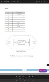
The Deye doesn't use pins 2-3 it's uses 5-6,check the rear pages of your manual to confirm yourself
 
From the manual I have on hand.

This is quite strange. My manual shows a standard pinout instead:

However looking again at the pinouts made me realize although the connected box is by any means a computer, it must act as a DCE, not DTE, that is, a device and not a computer, while my cable would expect to see a slave device on the other side, therefore I would need a cross cable:fp2
I should have one somewhere, or the necessary parts to make one. Will report back as soon as I can test it.
Tnx!
Just checked this manual is for the most recent manufactured inverters from march 26th 2024 so depending when yours were produced the pins might be different I would guess the manual supplied with your inverter should confirm which pins are used.
 
You also may not be using the correct protocol. Go to www.github.com and search on DEYE and then browse through all the projects (disregard the language unless you are interested in just one) which will give you some idea of the type of protocol used. You may find a project that you can use or modify to satisfy your needs
 
Yes thanks, done that, and looks like I'll have to learn Modbus and other things. Never too late:)
Anyway my immediate goal is to talk with the inverter, send a string and get a response, possibly not an error, then will develop further. The OrangePi is certainly overkill for the task, but I already was playing with them and similar SBCs. I already explored the idea to use a Espressif module with C or Micropython to send the most simple network packet with a few information, possibly a UDP packet smaller than a Ethernet frame, once per second, then will concentrate on the clients, which being completely free from any other framework could be really simple to set up.
Modbus is not difficult; just a byte array sent over a serial port. I usually have a function to create the byte array and send over a serial port rather than use one of the many modbus clients out there. Format is:
byte[0] = device address
byte[1] = command type, usually 3 or 4
byte[2] = hi byte of register to read
byte[3] = low byte of register to read
byte[4] = hi byte of count of sequential registers to read
byte[5] = low byte of count of sequential registers to read
byte[6] = hi byte of CRC
byte[7] = low byte of CRC

I find it is easier to first build and test my logic using an IDE on Linux or windows then migrate to a PI or esp32
 
Thanks for the explanation, I saw some boxes sold as Modbus interfaces and thought there was a lot more involved than simple data conversion. Yes, bringing a laptop up there will probably be a lot simpler, although the OPi is by any means a Linux computer with picocom and all the necessary to talk to serial ports.
Anyway, I made a null modem (cross) RS232 cable and still couldn't get a single char from the inverter, which suggests the pinout could be non standard, so will either blindly make a non standard cable as suggested on the more recent manual or wait for RS485 interfaces and go the Modbus way as I already have (albeit old and rusty) experiences in data transmission also between different different architectures (mostly IBM Power and x86) with different byte order and data sizes/alignment; will be a nice refresh of my old jobs knowledge:)

As for the manual, unfortunately I can't find my paper one, and don't even recall having been given one as I was looking at a downloaded one well before I had the inverter installed so it's possible I thought it was unnecessary.
I have a more immediate problem these days, and remote monitoring could be really useful: although everything keeps working and it passes the self test, the inverter repeatedly reports to be disconnected from the grid (or does it itself as I clearly hear a relay clicking when it does that). It happens only during day, and both the installer and me agree on 3 possible reasons:

1- Excessive CT cable length (roughly 10m, not screened and running near high voltage ones, yes it's a no-no, explanation follows).
2- Grid instability due to high demand in very hot days.
3- Heat. Installers built a small room with both air intakes and outtakes, and distances as written on the manual, but over there during these summer days it's hot like hell.

Sadly, the guys who last year laid down the two ducts for solar didn't properly check them and although they were completely empty and mostly straight, one is clogged somewhere while the other barely allows a couple wires to go through, so the solar guy after wasting hours trying to use them had to be creative using what was available to avoid making some cables run outside of the house, as the inverter is on the roof balcony and the main switch board with the CT two floors down. We already planned an attempt to use some good network cable to connect to the CT; I have plenty of spare CAT7A left from house wiring that I can use, although that clogged ducts could be a serious problem.

Will report back of any news/development!
 

diy solar

diy solar
Back
Top