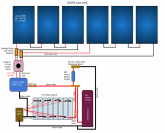
You are using two Midnite 15A breakers, one per string of 3. Depending on where you have that breaker/combiner, you can also use tat to shutoff either string, eliminating the isolator switch. Only thing I would add would be a battery monitor between the Inverter and bus bar. That would let you monitor inbound/outbound energy including your SOC if the monitor supports that. Some have Bluetooth, some connect to PC, others have a good digital display. Will uses various versions which he has reviewed.